https://web.archive.org/web/20220311020340/http://www.members.optusnet.com.au/nswmn/

https://web.archive.org/web/20220311020340/http://www.members.optusnet.com.au/nswmn/
Above photo is my Gosford complete with the Overhead. Click on the photo to see the Main North Album at Flickr

Tuesday, July 14, 2015

How Lucky are we to have a Hobby.

I have been reminded again, how lucky we are to have a hobby.

John a DCC modeller asked me if I could fix an electrical problem on his layout the “Tupper Lake and South Junction” as I had previously repaired his DCC system.


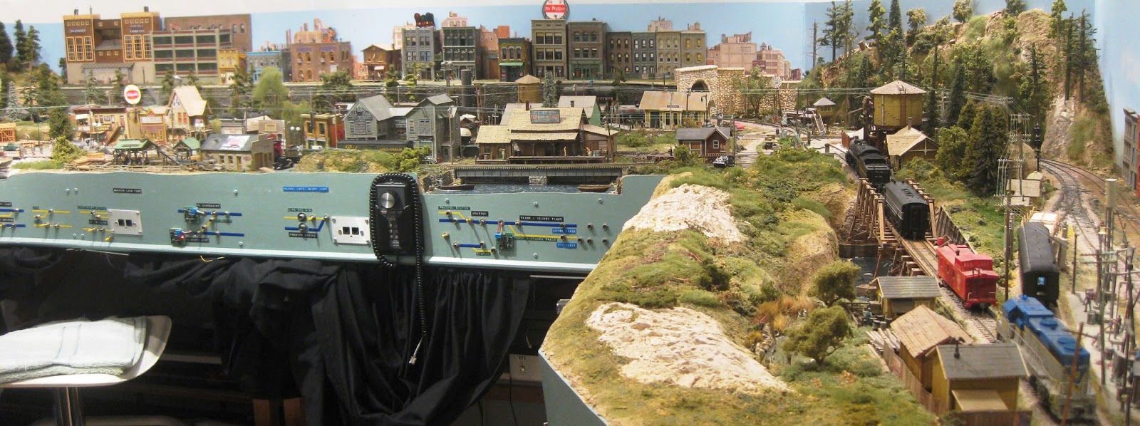
John and his wife live in a Unit with his layout in the 10’ x 12’ spare bedroom. The layout is finished with many finely detailed buildings and all the scenery is done. John’s grandson is installing lights in all the buildings.  

John has had both of his legs amputated and has to use a Frame, luckily the layout was mostly completed. Not to be sidelined, he is mobile enough to keep up his modelling. The third Bedroom has the Computer and a large Workbench where John does most of his modelling these days.

John is a member of the NMRA and is working on the Achievement Program that will hopefully culminate in him being awarded an MMR - Master Model Railroader. When I visited, he is working on a “Track Module” where he has hand built Points and a Crossover. John has 4 out of the 7 AP Certificates necessary to be awarded the MMR.

John’s wife Wendy said to me, we are very lucky that John has his model trains, it has kept him sane, active and busy.

Wendy’s comments reminded me, those that have a hobby are very fortunate, more so for us that are retired, there is always something to do that keeps us active.

My recent Blog entry about dismantling Keith's layout and his model railway Journey over 40 plus years, reiterates how lucky are we to have a Hobby. Both John and Keith are 84 years "young" and I hope I am as active and as young as John and Keith are, when I'm 84.

John and Keith, you two modellers are INSPIRATIONAL.

Click on the Slideshow Icon at Flickr for a photo tour of both John's and Keith's layouts.

John's "Tupper Lake and South Junction"  

For a YouTube video of John's layout, taken in May 2017, click here.

Keith's NSW layout

Thank You, John and Keith.

John passed away on 23rd June 2017. I have lost an "Inspirational" Friend. I did not know John for long. His Eulogy provided me an insight to his life, a devoted family man that lived life to the fullest with his wife Wendy always at his side. John leaves us but not before reaching the pinnacle of this Hobby, becoming an NMRA Master Model Railroader. John, you are more than a "Master" to us. You'll be sadly missed but remembered forever. John - Rest In Peace. 

Keith passed away in August 2020 - Rest in Peace, Keith.

Saturday, July 4, 2015

Speedo Car for Speed Matching Locos.

The most popular post on my Blog is my "30 MPH Max Speed Matching of all of my Locos", done in July 2010 with reference to my web page for making a Speedo Car. I recently made a Speedo Car for another modeller and I took some photos. Using these photos and the associated text you can make a Speedo Car for about $30 using one of your existing pieces of rolling stock.
Having a Speedo Car makes "speed matching" locos really easy.

An alternative to making the Speedo Car, purchase a module like the Train Speed 1 from TCS. See Ken Patterson's "What's Neat" series video, showing how he installed his TCS Speedometer

Parts for the Speedo Car.
Bicycle Computer from any Bike Shop. The one below is from Ecowell.
Casula Hobbies K wagon or similar. I assembled one from a kit years ago.
Metal Wheel Set for the K: 23.8 mm long 10.5 mm diameter (36") - Steam Era Part No W4 or similar.Your Wagon may be different, please check.
Magnet . I used the Wand supplied with Eureka Models sound locos and trimmed it to 6.5 mm see text.


Notes in Red added on 3APR2019.
  1. Mount the Sensor over the R/H Axle as shown in the Top photo.
  2. Cut Two Slots in the Sides of the K Wagon as shown.
  3. Carefully trim the Sensor's length with the Dremel as shown to eliminate too much overhang.
  4. Trim the sides of the Sensor.
  5. Drill a hole in the side of the Wagon to route the Sensor wiring back into the Wagon.
  6. I used a "square" Bike Computer as shown. Nov 2021, I used a $49 Ecowell BC10. 
  7. If necessary cut a Slot in the Floor for the Bike Computer's Clip, so it sits rigidly, see below.
  8. I used a K and M Axle with 10.3 mm Wheels and ground a "flat" on the Axle to easily secure the Magnet, see below.
  9. Using your Dremel, trim the Wand Magnet to 6.5 mm. DO NOT make it any longer. I made a 10.0 mm Magnet from a Wand and it DID NOT work with the Echowell BRI 8.
  10. Glue the Magnet to the Axle with 5 Minute Araldite and fit Axle to the Wagon.
  11. Trim the Sensor wiring for a neat fit.
  12. Before joining the wires, you have to CHECK the magnet/Sensor operation. Easier now.
  13. Connect the Sensor to a Multimeter, SET to OHMs.
  14. With the magnet "away" from the Floor, the Meter should show infinity (Open circuit).
  15. Rotate the Axle so the Magnet is CLOSE to the Floor, the Meter should show ZERO (short circuit).
  16. If the Sensor shows SHORT all the time, the Sensor will have to be RAISED above the floor.
  17. If the Sensor shows OPEN (infinity) all the time, the Sensor will have to LOWERED. Grind away the face of the Sensor and/or the floor.
  18. When the Sensor shows ZERO Ohms ONCE (close to the floor) in 360 degrees of Axle rotation, the Sensor and Magnet are set up correctly.
  19. Fit some 3.0 mm heat shrink to the two wires.
  20. Solder the connections then shrink the heat shrink. Note: The Echowell BRI 8 wiring is difficult to solder. The strands of the multi strand wire are covered with insulation. Use your Soldering Iron turned up to 450 degC to melt the insulation. Use the normal Temp setting to solder the wires together. 


Adjusting the Bicycle Computer for correct operation.

For the Bike Computer arrangement, the unit will need to be programmed with a "multiplier" determined by the diameter of the Wheel to provide a "one pulse" per revolution signal. Counting these pulses over time time, the Computer displays KPH/MPH.

Since we modellers want scale KPH/MPH for our scenario and the Wheel of the K Wagon is a "scale" 36 inches in diameter, we use the SAME "Multiplier", as above.

Using the Instructions, you'll find a value close to the one I used in my original Speedo Car and what I programmed into my new Speedo Car. That is 2873. For my Ecowell BC10, I again used "2873"  Check your individual Bike Computer Manual.

You need to program your bike computer with is "2873".

To check your calibration:
  1. "Mark" 3 feet of straight track on your layout.
  2. Operate a loco at 10 MPH as indicated on the Speedo Car
  3. Using this 36 inch "Speed Trap", time the loco.
  4. It should take 18 seconds.
  5. If shorter/longer then you may need to change the "Multiplier".
  6. Don't be too pedantic here - close enough is good enough.
For a good Speed Calculator see:

Scale Speed Calculator

From the above, hopefully everything has worked out okay and you're ready to "Speed Match" your locos.

While I use 30 MPH for my maximum speed you can use what ever speed you desire.