Adding the 48s to Werris Creek and Willow Tree, I needed to motorize all the Points to make it all work for running the 48s. I had to redo the track for the Diesel Terminal to fit the Peco Point motors, as the initial track layout was done in a hurry & it is hard to reach/see the position of the Points. When I added Willow Tree, I added the Point motors & components as I laid the track & even added the ballast.
Finalizing South Werris Creek & Willow Tree was a real challenge as I had to prepare for a hospital procedure in April that took me out of action & when returning, resulted in a major lack of motivation on the Main North.
I replaced the round table in the Family room with a 2 metre table I had downstairs & 4 chairs I found while walking the streets for exercise that the owner had put out for a council pickup.
With the extra bench space, I set up my wife Elley with her Puzzle Books etc & purchased her a Laptop to look at YouTube videos etc, at one end & setup my Laptop on the other end.
We now have plenty of room so the two of us can bash away at the keyboards together. Better still we're together as we face the challenges of getting older, together.
.JPG)
Last year, I'd already drawn up some basic plans of the 3 Control Panels I needed to make on pieces of paper. I needed to redo these in full scale. I'd previously made a crude Drawing Table using a piece of 300 mm wide timber, a Tee & a crude Set square for the the 45 degree angles, necessary for drawing up my Control Panels. Now that the 3 Control Panels are made and installed, I've decided to make a Control Panel for West Tamworth, I'll add step by step photos below.
All the parts can be purchased from Jaycar: 3.0 mm Aluminum Sheet, 3.0 mm Green LEDs, LED Bezels & all sorts of Toggle Switches, I use mostly DPDT. If a Semaphore signal is involved, I use a 3PDT unit. I've accumulated many Toggle Switches from the layouts I've dismantled including 4PDT units.
To operate the Peco Point Motors I made a 22.0 Volt D.C. home made Power Supply years ago & it's located under Broadmeadow. This Power Supply already powers Werris Creek and Port Waratah Control Panels so I just extended the 22.0 Volt feed going out to South Werris Ck, Willow Tree & onto West Tamworth.
Using a circuit, I saw in Dec 1994 AMRM from Gary Snow (shown right) - thanks a lot Gary for making operation of my Peco Point motors easier, I solder 2 x Diodes (IN4004 1 Amp Diodes) & test the Motor & Point at the Bench. Occasionally one Motor needs a little more power, done by adding a second 2,200 uF Capacitor.
Two wires are soldered to the "free" end of the two Diodes across the Solenoids.
The Negative of the 2,200 uF Capacitors are soldered to the Negative 22.0 Volt Bus.
One of the above two wires soldered to the Positive of the Capacitor, the other wire to the Control Panel Toggle Switch. These two connections may have to be swapped around to get correct orientation of the Point - done on the final installation.
Mounting of the Control Panels depended on the location. The South Werris Ck panel was mounted with a hinge so as it was easily accessible for wiring etc onto two brackets for a sloping Panel. The Willow Tree Panels due to the heavy people traffic in the aisleway, were mounted recessed behind the Fascia similar to how I mounted the Armidale & the Newstan Mine Panels so as they would not be fouled by an Operator. Doing this was a little more difficult but worth the effort.
I moved the South Werris Ck Signal Box further down the Main towards the Station, across from the Turntable. This provided more of a Hill that divides Werris Creek from Willow Tree at the doorway into the garage where Willow Tree is,
I added more Trees I got off a Mate around the rear of the Werris Ck Roundhouse & I crowded the Sidings with Trees, shown below, maybe not like the real Werris Ck but my Werris Ck is small and needs prettying up & trees do a wonderful job here. The Two Werris Ck UP Starting Semaphores are hard to see with all the new trees but Operators have to vigilant when driving the trains. I added a higher Fascia along the Yard to accommodate the Control Panel.
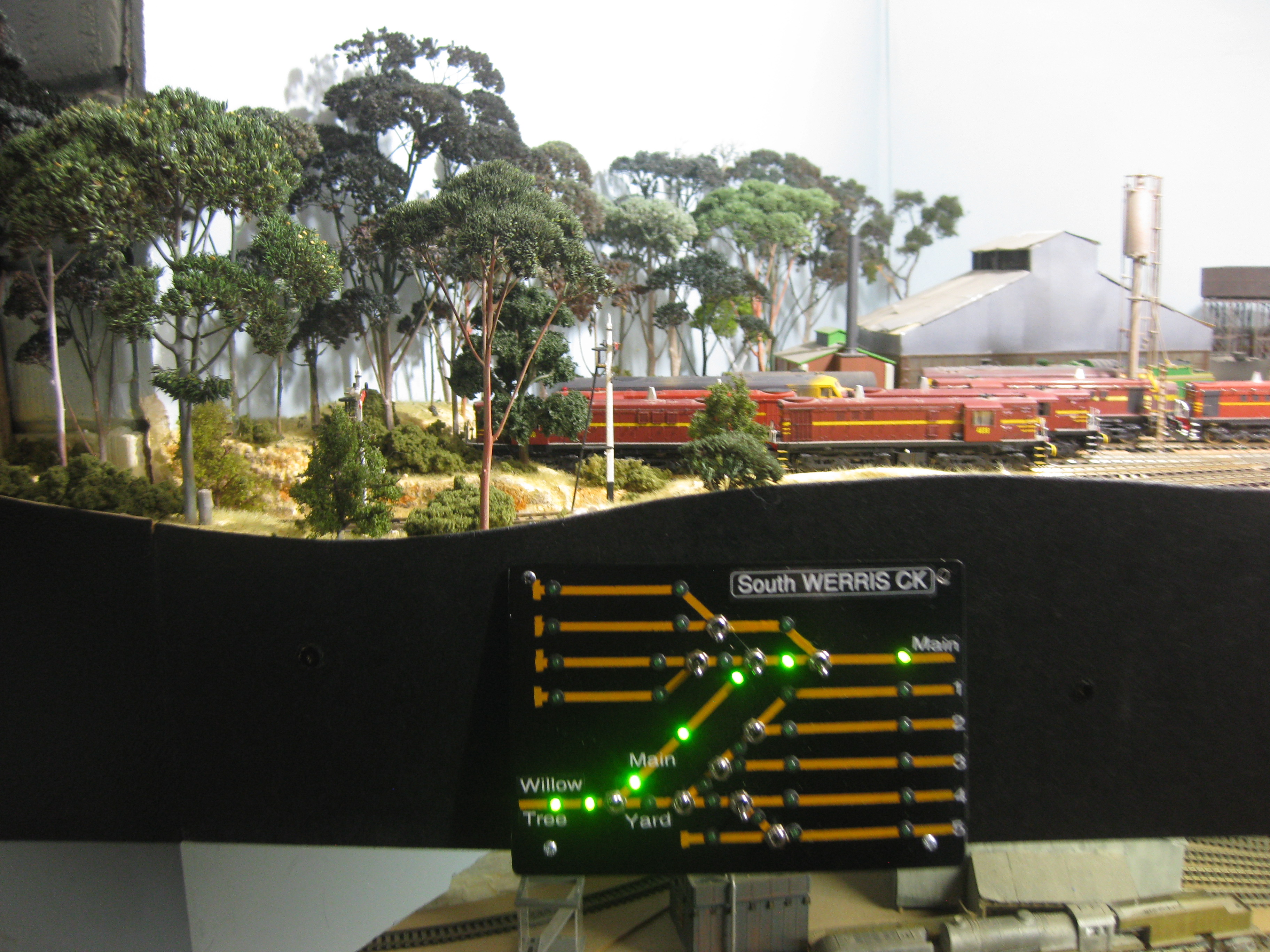
Werris Ck & the two Willow Tree Control Panels are installed & working as expected with the "route" shown with the appropriately illuminated green LEDs.
Willow Tree North Panel with the route shown by the green LEDs taking the Operator (train) along the "through" road into Werris Ck.
Willow Tree south Panel showing the selected route along the "Trough" road what I call the Main & not passed the Station. This configuration also illuminates the North Willow Tree Panel as shown above.
At the South Werris Ck Panel, I mounted a 3 Terminal 12.0 Volt Regulator powered by the 22.0 Volt supply onto a piece of aluminum for a heatsink, making a 12.0 Volt Bus going to each Control Panel for the operation of all the LEDs. This Voltage Regulator could be bypassed by installing a Resistor dropping the 22.0 Volts to approximately 12.0 Volts for the LEDs. I may add a resistor at the West Tamworth Control Panel, as the Heatsink is hot to touch & the current to the LEDs is 420 mAs.
Constructing the West Tamworth Control Panel.
Using the appropriate Plan I make a Control Panel from the Aluminum Sheet & I taped the drawn up "plan" to the Plate. I centre pop the location of the all the holes for the Toggle Switches and numerous Green LEDs for route identification,
Drill the appropriate holes - 6.5 mm for the Toggle Switches & 4.3 mm holes for the LEDs.
Then spray paint the Panel Yellow.
Using some 3.0 mm Lining tape purchased from Auto One, join the appropriate holes for the track & add dead ends if necessary. I did make a mistake here, I just blacked out the yellow track - easy.
Paint the Panel Black.
Remove the tape to show the Yellow "tracks". Install the 15 Toggle Switches & 54 LEDs
Now for the hard part, the LEDs need to be wired up to illuminate the appropriate route/Siding etc via one of the Poles of the Toggle Switch using a DPDT/3PDT or if a Semaphore is used. This requires lots of effort but worth it the end. I then wired up the Point Motors, connecting all of the 2,200uF Capacitors to the Negative wire of the 22.0 Volt supply under the layout.
The most important route is the Return Loop, powered by a Dual Hex Juicer from Tam Valley acting as an Auto Reverser, located under the track.
The West Tamworth Panel with the appropriate Sidings etc named using a Brother Printer. Operating the Glen Innes Mail, into West Tamworth, I leave the Barraba Mail Coaches at the Station then run the Mail into Armidale. If the Mail needs to be "turned" for operating as the UP Mail, then take the Return Loop. Back up the Mail via the Crossover into the Shunting Neck. Then into the Station. Then "back up" into Armidale ready to operated as an UP Mail, stopping at West Tamworth to picking up the 3 Barraba Mail Coaches on the way through plus double heading 3009, through to Werris Ck.
With the Return Loop being the most used section of the track at West Tamworth, I fitted a 15 Volt 3 Terminal Regulator at the suggestion of a Comment left below, to reduce the temperature of the "heatsink". The current to the 18 LEDs at 12 Volts was 270 mAs & with the 15 Volt Regulator it reduced to 210 mAs. The temperature of the heatsink is just luke warm now.
The recessed Panel located in the fascia on the Down end of the Station with the Silo in the background with the 3 Sidings storing the RU Wheat Hoppers.
Behind the West Tamworth Control Panel - what a mess but it works. All the White wires go to the Peco Point motors.
At the UP end of West Tamworth (3 Loops), there won't be a Control Panel as the Double Slip that's not used much with the only used Point for the "middle" road being used for the Barraba Mail Coaches. If necessary to operate the RU Wheat hoppers or from the Shed, then this will have to be done manually.
All trains are set to run into West Tamworth Station by Occupancy detectors on the Lift Up Bridge with the Bracket Semaphore also indicating to the Station. There is a Bracket Semaphore indicating the route through the Points into the Return Loop or to Armidale. I need to set up something automatic if Continuous running is necessary. I have to think about this as Return Loop running is the major operation here.
The operation through to the UP Main from West Tamworth is done automatically with Occupancy detection & Point Motor Accessory decoder, Marcus' version, see below:
The first 5 months of 2022 were quite wet with more mold prevalent downstairs. I spoke to a mate that suggested purchasing a Dehumidifier. These were scarce in June but I was able to purchase a Delonghi unit easily moved around the layout with the 4 casters, is now sucking out all the water in the air & hopefully reducing any new mold. Water has to be emptied from the onboard 4.5 litre tank unit but I can connect a hose for continuous draining, if necessary.

.JPG)

.JPG)
.JPG)


.JPG)
.JPG)


.JPG)


.JPG)
.JPG)
.JPG)
Your 12V regulator is probably getting hot as you are feeding it a 22V DC input. Linear regulators only a need a small voltage level above the output level (2 to 3 volts) to regulate. The rest is dissipated as heat. One workaround is to use a higher voltage regulator (eg: 15V) keeping in mind LED resistor values, another is to use separate 12V regulators at each control panel, spreading the current load across many instead of one.
ReplyDeleteHi Anonymous. Thanks for your reply. A 15 Volt Regulator would be a good idea as it won't increase the current through the LEDs by too much. I'll monitor the heatsink temperature. I'll monitor the current to the LEDs under different Toggle Switch combinations and probably use a combination of 5 Watt resistors I have here to drop the voltage. I'll look around for a 15 Volt Regulator on all the old circuit boards I have here, otherwise it may mean a trip to Jaycar. The other Control Panels there's no issue, it's only West Tamworth. I'm working on rewiring the Sidings & getting the Turntable to work so I can keep an eye on what's going on.
ReplyDelete