https://web.archive.org/web/20220311020340/http://www.members.optusnet.com.au/nswmn/

https://web.archive.org/web/20220311020340/http://www.members.optusnet.com.au/nswmn/
Above photo is my Gosford complete with the Overhead. Click on the photo to see the Main North Album at Flickr

Wednesday, October 9, 2024

Stay Alives.

Note: Disable DC operation in CV 29 & set CV 11 to “0”, when using Stay/Keep Alives.  

I have found with DC enabled (I always disable DC), the operation of the loco with no power (under Stay Alive), is very much reduced and the loco movement is jerky, using Soundtraxx Tsunami TSU-750/1000 & Econami steam decoders with Soundtraxx Current Keepers or TCS KA2s. 

Train Control Systems (TCS), have two external Keep Alive modules and numerous decoders that include the Keep Alive, making stalling/hesitations a thing of the past. These are the:

KA1: Size L26.7 x W16.4 x H7.5 mm providing 3 – 6 seconds Stay Alive (TCS specification).

KA2: Size L33.0 x W11.6 x H8.8 mm providing 13 to 40 seconds Stay Alive (TCS specification).

Both the KA1 and KA2 are provided with 2 wires, where:

1.  The BLUE wire is connected to the Function Common - DC Positive (Blue wire). For Tsunamis, this is NOT the RED Capacitor wire.

2.  The BLACK with white trace wire, is connected to the DC Negative of the decoder.

Many decoders do not provide a DC Negative connection. 

The “DC Negative” is easily found at the at the Anode ends of the two Input Diodes (Bridge Rectifier), that have their Cathodes (Band) Ends connected to the Track Input, more details shown below.

I have fitted KA2s to HO locos equipped with Soundtraxx Tsunami (TSU-1000, TSU-750 & AT-1000), Soundtraxx DSD100-LC etc, Loksound, TCS, NCE and other decoders (shown below), that provides between 5 and 60 seconds of stay alive, depending on Motor current draw etc.

The documentation says when connecting these units to TCS decoders, program the TCS decoder’s CV 182 to a value of 2.

When fitting the KA1/2s to other brands like Soundtraxx, there is no need to program CV 182.

See Bruce Patrarca aka Mr DCC, demonstrating the benefits of these Keep Alives on his Club layout.

For more details and programming when using the KA1/2s, see the notes below the photos. 

Connecting the TCS KA1/2s to Soundtraxx Tsunami Decoders.


1. Do NOT connect the KA1/2 BLUE wire to the RED wire to the Capacitor. If you do, the KA1/2 will only feed the Microprocessor and the sound portion of the Tsunami, while the sound will go on for 30 or so seconds, there will NOT be any stay alive to the Motor, causing it to stall/stop, immediately the loco experiences a power interruption (dirty track), explained in the schematics below.

2. I have found that if you remove the 220 uF Capacitor altogether, I could not read CVs of the Tsunamis on the Program Track. Replacing the 220 uF with a smaller 100 uF 16 Volt Electrolytic Capacitor, I was able to read CVs.

3. If you are having problems finding space for the 200 uF Capacitor in your loco installation, connect a 100 uF 16 Volt Capacitor, connected directly to the two pads (+ & -) of the AT-1000 Tsunami.

Installing the TCS KA1 or KA2 Modules.

Photos of my previous 4,700 uF Stay Alives are included with the Tsunami AT-1000, to show/explain on how to connect the Keep Alives. 

Tsunami TSU-1000

  1. Blue wire to the Blue Function Common wire &
  2. Black with white trace wire, to the Black wire connecting the 220 uF Capacitor (not the Black Pick Up wire).

Tsunami TSU-750

  1. The Blue wire to the Blue Function Common wire &
  2. The Black/White trace wire to the Green/Yellow wire.

Tsunami AT-1000

  1. The Blue wire to the Blue Function Common Pad (Pads 2 or 9) &
  2. The Black/White trace wire to the Black wire connected to the 220 uF Capacitor (not the      Black Pick Up wire) or to the Anodes of either of the 2 Diodes with the Cathodes (bands) ends connected to the Track Pick Up wires.

Shown below, the TCS KA2’s Black/White trace wire is connected to the Anode end of one of the Input Diodes & the Blue wire is connected to the Function Common on an AT-1000 decoder. 


 Tsunami GN-1000

 The GN-1000 is different than other Tsunamis in that they have:

  1. An On Board 1.5 Volt Regulator for 1.5 Incandescent lamps. Do NOT connect to Tabs 2 and 11 like that on the AT-1000.
  2. The “+14 Volt” Pad near the Input Diodes is isolated from the Motor. If you use this connection there will be NO stay alive for the Motor.

Connect the TCS KA1/2 Stay Alive’s wires:

  1. Blue: to the Cathode (Band) end of the Track Input Diode adjacent to Tab 11.
  2. Black with White trace: to the Anode (NOT the band/stripe) end of the Track Input Diode adjacent to Tab 12 as shown below.

Above schematic is courtesy of Ulrich Models. 


Econami 21 Pin

The “Pin Out” details of the ECO 21 Pin can be found at Bryan Vinaco’s SBS4DCC Web site at:

http://www.sbs4dcc.com/tutorialstipstricks/21mtcconnector.html

For the ECO 21 Pin, I connected the Keep/Stay Alive’s to the Loco’s Circuit Board (motherboard)and NOT to the 21 Pin decoder, as:

  1. Blue - Positive: to the Function Common (BLUE) to the Loco Lights etc or to Pin 16 (not shown in the below photo).
  2. Black/White trace – NEGATIVE: to Pin 20 as shown in the below photo. 


Alternatively, the Stay/Keep Alives could be connected to the Input Diodes, see below under the heading of “To find the DC Negative of ANY decoder not shown above”  

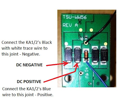
Soundtraxx in Bachmann, Intermountain & Proto.

The photo below shows the Stay Alive connections for a Soundtraxx equipped Bachmann RS-3 with the TSU-WW56 Circuit Board. Marty C suggested that Intermountain & Proto locos are the same.


QSI Revolution A.

NOTE: The Revolution A has a 5.0 Volt regulator & a 220 Ohm resistors included on the Board for LEDs or 1.5 Volt Incandescent Lamps. You CANNOT connect the TCS KA1/2’s BLUE wire to this 5.0 Volt Tab.


Connect the TCS KA1/2 as explained below and shown above.

  1. The Blue wire to “other” (Cathode) end of the Diode with the Anode (no stripe) that’s connected to either Track Pick Up.
  2. The Black/White trace wire to the “other” (Anode) end of the Diode with the Cathode end (stripe) that’s connected to either Track Pick Up.

QSI Revolution U 

  1. Connect the BLUE wire to the BLUE decoder wire.
  2. Connect the BLACK/White trace wire to the Capacitor’s BLACK wire.

 Loksound V3.5 

        See Streamlined Back shop 4 DCC web site entry at:

SBS4DCC - ESU LokSound 52400 V3.5 "Keep Alive"

Loksound V4.0

See the appropriate Manual.

Soundtraxx DSD100-LC

  1. Remove the heat shrink from the decoder by slicing down one edge with a Razor Blade etc.
  2. Connect the BLUE wire to the BLUE decoder wire.
  3. Connect the BLACK/White trace wire to the Anode as shown with the yellow wire.
  4. Re-install Heat Shrink.


 Soundtraxx DSD-AT100LC

  1. Connect the BLUE wire to the Function Common Tab or to the positive connection as shown
  2. Connect the BLACK/White trace wire to Anode as shown below.


DSD-B280LC

  1. Connect the BLUE wire to the Function Common - Pin 7 or to the positive connection.
  2. Connect the BLACK/White trace wire to Negative connection at the Anode as shown below.


Soundtraxx DSD-LL110LC

  1. Connect BLUE wire to the Function Common (Pin 7) or to the positive connection as shown
  2. Connect the BLACK/White trace wire to Anode of the Diode as shown below. 


Soundtraxx DSD150

  1. Peel back the shrink wrap from the 9 Pin Socket end, as shown.
  2. Connect the Blue wire to the decoder Function Common BLUE wire.
  3. Connect the Black wire to the Diode (Anode end), as shown below.


 NON Sound Decoders. 

 TCS T1

  1. Connect the BLUE wire to the Function Common Blue wire
  2. Connect the BLACK/White trace wire to the Negative connection of the decoder’s Bridge Rectifier as shown with the Green wire.


 NCE D14SR

  1. Connect the BLUE wire to the Function Common Blue wire
  2. Connect the BLACK/White trace wire to Diode/Capacitor junction, shown with Green wire.


To find the DC Negative of ANY decoder not shown above:

  1.  On the decoder, locate the 4 Diodes (Black rectangular blocks) used to rectify the DCC from the track, generally on one end of the decoder where the wires from the track pick-ups are secured/soldered to the decoder.
  2. The ANODE ends of the two Diodes that have their Cathodes (Band) Ends connected to the Track Input, form the DC NEGATIVE.
  3. The TCS T1 has a Bridge Rectifier. Connect the Black wire to the Negative Pad of this Bridge Rectifier.
  4.  Smaller N/Z Scale decoders like the TCS M1, have really small Diodes or with decoders that you cannot identify the Input Diodes, to locate the DC Negative:

          a.  With the decoder powered.

b.  Connect the RED Lead of your Multimeter, to the decoder’s Function Common.

c.   Probe with the BLACK lead of your Multimeter around a large (well compared to the rest of the components) Orange or Brown block (a Capacitor).

d.  One end should be the DC Negative, like where the Green wire is connected on the NCE D14SR decoder, above.

    5.  Hopefully you’ll find the DC Negative.


Perceived issues when using Keep Alives.

If there is communication with a KA2 equipped loco, it WILL stop when commanded to. The loco will stop at the station, stop when switching loads, not end up in the Turntable Pit etc.

But

Locos will keep running when an un-powered block is encountered like when using signals etc. You have to take this into consideration if you are using a Keep Alive.

Using Service mode of programming (the Program Track) may be difficult, see next.


Programming with KA1/2s.

I have found that programming a decoder (Tsunami) with a KA2 installed, on the Program Track using a Soundtraxx PTB100 Booster with my NCE Power Pro unit, there are instances when reading CVs, returns a value of 255 for the CV.

The theory to read CVs, is that the Command Station instructs the decoder to pulse the Motor according to the stored CV value. From these pulses of current from the C/S, the value is displayed. The only problem is a charged up KA2 or the Command Station may supply the pulses of current. If it is the KA2 supplying the power and not the Command Station, then there will be no pulses of current from the Command Station pulses to interpret to display the CV value, hence the 255 display.

In practice on the Program Track, if you get a 255, then try again with a discharged KA2 and try again. If you still get a 255 read, then you have to disconnect the KA2. I get successful reads of CV about 80-90% of the time.

Except for the initial read of a decoder after installation or troubleshooting why a decoder does not work, I use “On the Main – POM” mode of programming using Decoder Pro, where there is no issue.


More details of the Stay/Keep Alives.

Relative sizes of the Stay Alives I have used from Top L/H Counter clockwise.


TCS KAT14T1. T1 Motor only decoder including KA1 Keep Alive components.

TCS KA1 Shrink wrap removed showing 6 x 0.22 F 2.5 Volt Capacitors.

Lenz Power 1 Module (USP). 1 x 1.0 Farad 2.7 Volt Capacitor.

TCS KA2 Shrink wrap removed showing 5 x 1.0 Farad 2.7 Volt Capacitors.

 4,700 uF 16V Electrolytic Capacitor as per my previous Stay Alive.

I have been using SIMPLE Stay/Keep Alive for years.

This comprised of the largest value capacitor I could fit into a HO loco, namely a 4,700 microfarad 16 Volt Electrolytic capacitor, a 100 Ohm resistor to limit the charging Inrush Current and a 1.0 Amp Diode to bypass the resistor, when the Capacitor discharges (supplying Stay Alive).

Components have become smaller. You can now purchase for less than a dollar, a 1.0 Farad 2.7 Volt Super Capacitors in 10 mm x 6.3 mm package.

To use the 2.7 Volt 1.0 Farad super capacitor in our 12.0 volt models:

Electronics can be are used to convert this low voltage energy into what the model needs, as Lenz has done with the USP, see below.

Or

Connect the 5 or 6 Capacitors in SERIES as to what we and TCS have done.

The electronics that Lenz has used with the Power 1/2 modules (USPs) does some extra things but can only be used with a Lenz Gold or QSI Titan decoder due to an extra Charge wire/connection is necessary. I have a YouTube video demonstrating that the decoder responds to commands (direction change etc), while running on Stay Alive power.

The TCS KA1 uses 6 x 220,000 uF 2.5 Volt Capacitors, while the KA2 uses 5 X 1.0 Farad 2.7 Volt Capacitors.

When connecting Capacitors in SERIES, using similar value Capacitors the effective capacitance Ct = C/n and the operating voltage of the package = 2.7 x n. Volts, providing an effective capacitance and operating voltage of, for the:

         KA1: 36,667 uF (microfarads) at 15.0 Volts.

         KA2: 200,000 uF (microfarads) at 13.5 Volts.

Apart from the 5/6 Capacitors of the KA1/2 there is a Diode and a 150 Ohm resistor, making what I call, a simple Stay Alive, the same as my 4,700 uF Stay Alive BUT with amazing differences. Comparing the 4,700 uF Stay Alive, the KA1 at 36,667 uF is has 7.8 times more stay alive energy and the KA2 at 200,000 uF has 42 times more providing much more stay alive than the quarter of a second, the 4,700 uF unit does, for a similar size package. Now it can be seen why these Keep Alives from TCS are so good.

But the best thing yet, the KA1 and KA2 can be used with ANY decoder.

Lenz Power 1 Module (USP) can ONLY be used on decoders that support USP, like the Lenz Gold and the QSI Titan. The energy stored at 2.7 Volts on the 1.0 Farad Capacitor has to made into a voltage that is suitable for a 12 Volt Motor, by some electronics comprising of what I can see, a small Coil, 2 x 6 Pin ICs, an 8 Pin IC, a Diode a Transistor/FET and numerous other components, provide the stay alive power. The high impedance input of the Gold decoder allows packet information, changes in direction, speed etc to get through to the decoder while running on stay alive (dead track) as evidenced on the Gold/USP YouTube video

Some years ago a modeller friend asked me to install Lenz decoders into his Bemo HOn3 fleet of locos. One unit a 4 wheel Tractor/Shunter was a real problematic runner, continually stalling/stopping in the Yard on his Exhibition layout. I installed a Lenz Gold/USB combination, resulting in smooth running through the Yard. He was ecstatic. This installation was a real challenge, fitting in the Gold plus USP into the small Cab but was worth it. I have since installed USPs into a few of his problem runners with similar great results.


Why do we need Stay/Keep Alive.

Dirt has been the enemy of model railroaders since we used electricity to operate locos. We have been able to put up with it, what has changed.

The introduction of SOUND locos.

Many modellers are building their dream layout in un-sealed environments where the air quality is not as clean as I would like it to be.

When a NON Sound loco experiences a power interruption from dirty track, gaps at turnout frogs etc, there would be a slight hesitation that in many cases would go un-noticed but with SOUND locos, you hear this hesitation with the sound disappearing them coming back on as the processor in the decoder stopped and started up again. This becomes quite annoying. Track cleaning isn’t the model railroader’s favourite chore, so I would persevere until it became unbearable. Applying CRC 2-26 to my track has helped immensely with reducing these sound reset interruptions.

Locos without flywheels and that is more than half of my steam locos, would most probably stop at these power interruptions, making this inconvenience a real hassle now.

On top of dirty track/wheels there are plenty of other things that contribute to a loss (interruptions), like:

  1. Track geometry/alignment. 
  2. Gaps/Insulation at Points/Turnouts Crossings etc. Many chose Peco Electrofrogs or similar to reduce the unpowered area around the Frog.
  3. Locos with small numbers of wheels and pick-ups, no Tender Pick-ups etc.
  4. Brass, Brass/White Metal DJH Kits etc where one side Drivers/One Bogie picked up positive and Tender/ other Bogie picked up the negative.
  5. Poor contact at Drawbar and the Bogie Bolster.
  6. The material wheels are made from can have an effect on pick up. Some materials are better than others and I am not into replacing them.
  7. While the weight of a loco may be enough, due to where it is located, the loco may be un-balanced effecting traction and pick up, especially when over Points/Turnouts etc.
  8. Tender Pick-ups seem to be unreliable (example C32 and C35).

Rectifying some of these issues is possible but some are way out of league of many modellers and fitting a Keep Alive will hide these issues and result is better running.

Fitting Keep Alives does not mean you can eliminate track/rolling stock maintenance. 


My NSW 4-6-4 C30 Tank Steam loco Keep Alive Installation.


As soon as I was able to get the TCS KA2, I installed it in one of my most problematic locos, a NSW 4-6-4 C30 Tank Steam loco.

During an operating session on my layout, this loco is scheduled to run the local Toronto Passenger from Fassifern to Newcastle and back again, a total run of about 150 feet but through two Peco Insulfrog Double Slip Points, twice and many Points/Turnouts. The C30 regularly stalls and I could not install a 4.700 uF Capacitor plus a TSU-750/Speaker. This loco was in desperate need of a TCS KA2.

I moved the Motor forward by about 5 mms to get the Motor out of the Coal Bunker area and modified a KA2 by cutting it in two sections, 3 Capacitors on one side & 2 Capacitors on the other side with both sections wired together, see photo above.


As I add ballast to my layout, I'm making my Points/Turnouts more reliable by linking the adjacent Point and Stock Rails as shown by the Wiring for DCC site but I am leaving the 45 -50 mm Frogs, DEAD (i.e. un-powered) and this loco negotiates them easily.

I/we operate all the Lower Deck Points/Turnouts manually (by finger) on my layout as I/we follow the train around. The fitting of a KA2 into the troublesome short wheel based locos like the C30, Brass and Brass White metal locos, now saves me adding Tortoises, Switches etc to these Points/Turnout, saving me heaps of money and time that is so precious, now we are getting older.

For those that do not know what a HO 13 cm (5 Inches) long NSW C30 looks like, here it is equipped with a Soundtraxx Tsunami TSU-750, a MRC 20 mm Speaker with the back removed and secured to the Cab Roof and now with a cut in two KA2 under the Coal Load.


For more details on how the Tsunamis work and other details, see my first “alive” page archived thanks to Mark Roach, at:

http://wayback.archive.org/web/20120729061658/http://www.members.optusnet.com.au/mainnorth/alive.htm                                      


Making Stay Alives.

The 1.0 Farad 2.7 Volt Capacitors can be purchased from Digikey at: 

https://tinyurl.com/4xb7ddzm

You could also purchase the 2 Diodes & resistor but I bought these at my local Jaycar. I made up Stay Alive Kits.

Connecting the 8 components for a Stay Alive can be in any shape/configuration needed to fit the Stay Alive in the available space, so long as the connections are made as per the Stay Alive Schematic.

The five 1.0 Farad 2.7 Volt Capacitors are connected in SERIES.

    Capacitors Leads:
    NEGATIVE is adjacent to WHITE STRIPE on     the Case.
    POSITIVE is the LONGER Lead.

    With the Capacitor’s Negative Stripe on the Left.

    Bend the two Leads with an “Angle” as shown.


Place some Blu Tak on the edge of the Bench.

Place all the pre-bent Capacitors with their Leads "pointing out" a little.

Make sure the Negative Lead of ALL the Capacitors are on the same side.


For each "joint", place one Lead over the other & solder the Leads as shown

Trim the Leads - Do NOT trim the outside two Leads.

Press the soldered connections into the space between the Capacitors.


On the OTHER side of the Capacitor Pack.

Place the 13.0 Volt Zener Diode with the Black Band to the POSITIVE end of the Capacitor Pack

Bend the two Capacitor Leads around the Zener Diode's Leads as shown & solder.


Connect the 100/150 Ohm Resistor & Diode in PARALLEL as shown & solder together.

The Silver Band of the Diode becomes the Stay Alive's POSITIVE Lead & connected the the Function Common (Blue Wire).

The OTHER end is connected to the Capacitor Pack's POSITIVE end as shown.


A few examples in my NSW Locos.


Eureka Models 50 Class with all the Capacitors in row down one side of the re-positioned QSI decoder.


Auscision 45. Capacitors arranged into a two row “5 Pack”, to fit them in a shorter but wider “position”.


Trainorama 48 Class 
4 Caps are in two rows & the fifth Cap is placed in the position where the Crew, “was”.


Friday, March 29, 2024

NCE's new PH5 Power Pro & DCC Meter.

NCE has released a new Power Pro system, the PH5, available from the Model Railroad Craftsman & their Dealers.

As a beta tester for NCE, I was sent a PH5 to evaluate & test on my layout in Dec 23. PH5 features:

  • 5 Amp capacity
  • A USB Port instead of a Serial Port.
  • Read CVs without a Program Track Booster.
  • More memory & faster Processor.
  • Upgrading from the Internet via the USB.
  • Faster loco selections for Wireless Cab06s. 
  • Supplied with an External 19.0 Volt 5.0 Amp D.C. Switch Mode Power Supply.

For more details, see DCCWiki 

I downloaded a test version of JMRI & got Decoder Pro working. You'll need to have JMRI test version 5.7.1 or later for the PH5.

I have 8 Power Districts on my layout, controlled by NCE EB1s. I reprogrammed my EB1s with the following CVs:  CV 135 = 0 & CV 129 = 1. I also checked the Trip Currents for each EB1 (see your Manual).

Released at the same time was the combined DCC Meter & Analyzer. As shown it displays  Volts & Amps. I recommend everyone to have an Ammeter to know how much current is being drawn by the layout, easily mounted in you layout's Fascia, available from MRRC. Click here for the DCC Meter Manual . See see my Ammeter Blog entry to build an Ammeter for $3 that includes your 10A Multimeter. 

Thursday, November 23, 2023

Derailments, Track & Speed Issues.

Operating two of my signature trains, the Double Garratt 1200 ton Newstan Coal train & the Northern Tablelands Express 7 Car DEB Set, both shown below, passing my Newstan Mine, on Fassifern Bank, I had some derailments. Some maintenance is way overdue.


Derailments are a pain in the butt anytime, especially with a Garratt but in tight spaces in the Newstan Mine Shunting Neck or the the DEB Set under the Overhead Wires, they're intolerable.

For the derailing Garratts, I first checked to see the Sound Tubes were in their correct locations on the Front Buffer Beam as dislodged Tubes cause the Pony Trucks to derail. 

The Newstan Mine Shunting Neck starts off from the Loading Bin through two sets of Points under Fassifern Bank (through the Black Hole in the above photo), then with two lengths of Peco Streamline track set at 20 - 22 inch radius to keep it inside the Fassifern Bank fascia & underneath the Sulphide Works with a further 2 metres of straight track under Sulphide Junction with minimal clearance. My Eureka Models Garratts are supposed to be able to negotiate 18 inch radius track. 

Using both Garratts, I found that the "outside" Drivers "rode up" on the outside rail, as it tried to negotiate the same 20 cms of the curved track, ultimately de-railing, in a bugger of a place. 


Using a smaller wheel base locos like the 50 Class, it negotiated this "tight" track okay. I could not fit my  NMRA Track Gauge in between the two rails, at this "tight" spot, while the rest of the track was okay.   

I lay a new section of track, soldering two lengths of Peco Flexitrack together & letting the track find it's own best lie then secured to the road bed with screws. I repositioned the LED Strip Lighting & trimmed some of the above track "road bed", creating a bit more clearance. This job took a few days with lots of swearing. 

One of the Garratts had it's Kadee fitted providing a "close as possible" coupling with the BCHs, looks good but on small radius curves, the Pony Trucks were touching the Coupler Box. I trimmed all the Coupler Boxes & fitted the Coupler to the "outside" hole, providing maximum clearance. I tested the Garratts numerous times on this Shunting Neck, with no derailments. Time will tell. 

To see my 1200 ton Double Garratt Coal train from Newstan, see my 2020 YouTube, below.


The 7 Cars of my Northern Tablelands Express have 2 axle Bowser bogies. Having only 8 wheels to pick up the power is fraught with power interruptions. To improve the pick up, I  have  have permanently wired the 4 Cars together, providing all wheel pick up. Same for the 3 Car Set. 

The 4 Car Set has two Motors & two Speakers from the one decoder with one of my Stay Alives, & with the two wires for pick up, making it 6 wires in the harness. The 3 Car Set only has one motor & one speaker making it a 2 wire harness, just for "pick up".

Recent running of the 7 Car set from Werris Ck to Sydney & back, the second Car of 4 Car continually derailed at Points. Repositioning of the harness & securing it to the roof inside, reduced the derailments. Running under the Overhead Wires of my new Gosford to Sydney section, these derailments became intolerable. 

More needed to be more done. The "fine" wheel flanges on the Bowser Bogies, need all the help they can get to negotiate the Frogs on my Points. While most of my Points have a .015" (15 thou) styrene glued to the Check Rail on the Points, I fitted more 15 thou styrene, to the remaining Points. 

With these above "fixes", derailments of the Express were all but eliminated. You cannot eliminate Operators running "against" an incorrectly set Point.  

Two Operators suggested the DEB Set was not travelling fast enough in sections of the layout. I had noticed this also. Looking for an easy fix, I decided to look at the Track Voltage. Down to 11.8 Volts DCC. I switched out my Ammeter that "robs" about 1.0 Volt but it made minimal difference. 

I adjusted both decoder's "Speed Tables" to provide the maximum speed & the 4 Car Set was only 18 MPH, while the 3 Car Set was 55 MPH. 

With the 4 Car Set upside down on the Workbench to clean the wheels, I noticed applying a Cotton Bud to the wheels of one of powered Bogies, it nearly stalled, while the other bogie was okay. It was time for a "Service" well at least some form of lubrication. I had not previously "oiled" the Motor/Gearbox Bushes on this DEB Set. 

I cleaned & oiled the bushes & added a drop of thicker oil to the gears & the stalling was gone. I did the same with the other "End" Car Now the 4 Car set had a Top speed of 60 MPH. What an improvement a little oil does & I used to have a Workshop fixing cars. They also let me loose on aero planes but I was a "Conehead", not a "Greaser". I lubricated the 3 Car Set.

I speed matched both Sets to provide 5/10/15 & 20 MPH at the appropriate Speed Step, with a Maximum of 30 MPH at Speed Step 28. I do this to all my locos & I use 28 Speed Step mode, so when an Operator sets the loco to Speed Step 20, the loco is travelling at approximately 20 MPH. To see my Speed Match Blog entry click here.  

Now with Speed to burn with the DEB Sets & as the train is an Express,  I decided to "up" the Maximum Speed to 40 MPH for the DEB Sets. The passengers will appreciate it.

To see my Northern Tablelands Express run to Sydney & back, click below on my 2020 video. 


Saturday, November 4, 2023

Fassifern Station Upgrade & the NMRA Layout Tour.

Upgrading my Stations has been a long time coming, the latest is Fassifern the second last one on the lower deck, then it's onto Ourimbah. Not much has been done lately. 

I made new 1.3 M long platform bases, using 19mm thick Pine. I added styrene to the platform edges then covered the platforms with a Sand mixture. I added a Fence to the Down Platform & "adjusted" the Footbridge a little for the Steps down to the Platforms & Road (down side).  

I used my original station buildings, a Suburban Station kit for the Island Platform & the the two small buildings on the Down platform then added some Platform Lights including the Nameboards. 


I will have to upgrade my Bracket Semaphore to be one of Ray Pilgrim's Fassifern's Double Bracket Semaphores with the prototype shown below. Because of the Wakefield Road Bridge, drivers could not see the Signal, so a Double Unit was made.


I'll replace my Dale Richard's Bracket Semaphore, built years ago. I have the Wakefield Road Bridge but my Fassifern Bank is at "right angles" to my Fassifern. I may add some Semaphores for the Toronto line.  


Looking north through Fassifern, the 1200 Ton Double Garratt Coal Train backing out of Newstan Mine & crossing over onto the Down Main. The Garratts will stop when they've passed the end of the Platform, then reverse, accelerating through the Station to attack the 1 in 40 Fassifern Bank, with some speed.


The Australasian region of the NMRA had a Convention at Rosehill over the October Long Weekend,  where I had volunteered for Convention Attendees to visit my layout on the Friday, Monday & Tuesday. This above upgrade was just completed prior to the Layout Tours, Visitors in the Morning & a 3 hour Operating Session in the afternoon. I had about 30 visitors. 

I knew my Queensland Mates were attending the NMRA Convention, so I offered to have them over for Dinner, coming on Sunday night, where I cooked Spaghetti Bolognaise, topped off with a Nanna's Apple Pie & Ice Cream & plenty of Cakes. Then we got to run some trains but mostly had a yak fest. I had a ball. Thanks Darren, Bill, Craig, PK etc. for making it to the Main North. Thanks for the photo Darren & Craig. 


During the 3 Operating Sessions, I asked for a volunteer to "run" my Double Garratt 1200 ton Coal train from Newstan Mine using my Operating Card & asked them how to improve the "running around" of the train at Broadmeadow to haul it into Port Waratah, without "running" onto the mainline at either end of Broadmeadow. as it's been suggested that what I need to do. The 3 different Operators had fun to say the least. Geoff, the last Operator worked in the Signaling Department of the railways & suggested I needed a few more Signals. Ray, I may order some more.

The Northern Tablelands Express DEB Set & the Garratts of this above train, had a few de-railments during the weekend, fixing why they de-railed, is my next Blog topic. 


Thursday, August 3, 2023

Gosford Upgrade.

Gosford was always going to be a BIG job & I was always putting it off, shown at the right before the Upgrade.

With the Overhead across the Broadwater into Gosford (last Blog entry), I decided to get on with upgrading it.

Prior to ballasting, I fitted 4 x Rapido Un-couplers to appropriate locations on the Main & Loop with their operating Switch on the Control Panel for north of the Station Un-couplers. For the UP Main Un-coupler on Platform 1, the Switch is on the Fascia. More details on Rapido, see my Uncouplers Blog entry.

On the lower deck of my layout, I manually operate the Points for most locations, that included Gosford but  knew this would be difficult with the Overhead installed. Years ago I tried a Rod in a Tube connected to a Slide Switch for one of the Points & this worked okay. 
Gosford Yard has 10 Points that'll be under the Overhead & I intended using this method. I installed 15 more of the Rods/Tubes then added the Ballast, using Chuck's Martins Creek that's no longer available. adding the Slide Switches after the ballast dried (shown left). Note the "test" Peco Point motor is in the foreground. 

For years I've been using a curved Island platform salvaged from another modeller's layout.
Instead of building another one, I modified this one by adding a strip of tapered timber to the straight side (platform 2) & re-aligned  the curved "Back Road', (platform 3) track. 

I added Styrene Strips to the edges of both platforms & surfaced the tops with a white sand/black oxide, mixture.  


The tracks south of Gosford already had their Rods/Tubes/Switches installed & were operated with a small knob at the fascia, shown left.

I considered using this method on the Points in the Yard but the aisle at the northern end is very narrow & I could see Operators fouling the knobs, inadvertently operating a Point. This is why I was going to fit the Slide Switches in hole in the fascia.

The Overhead installation was completed. The 90 degree turn was quite fiddly. Catenary wires were trimmed/lengthened to enable having single Stanchions crossing 3/4/5 tracks in the Station & through the Yard.

The Turntable is located at the southern end of the Station, adjacent to Platform 3, due to lack of aisle width north of the Station. 

I added a Harmen Coal Stage until I build a Hodkinson Electric Crane that was at Gosford in 1965 & a Water Tank that's missing it's Water Treatment Shed, that I hope to build one day.


While waiting for the ballast to dry, I experimented with adding a Peco Point Motor to one of the Rod/Tubes arrangements directly to the baseboard without the Peco Mounting Bracket.
I warmed to this new method but to make this work, I'd have to make a Control Panel, a major job. 
I decided to go with Point Motors & a Control Panel. I added 10 Point Motors secured with a screw with the appropriate Capacitor for my Capacitor Discharge method (see previous Blog entry), at the edge of the baseboard.  

I made a Control Panel mounted at eye level on the fascia of the track going to Werris Ck, above North Gosford. I used my usual method of using Toggle Switches & illuminating the Green LEDs for the route selected - more details see my Control Panel Blog entry.

I made a foam Cover to hide the Point Motors, secured with 4 screws. I added Showground Rd at the edge, 4 houses & a Car Park, at the Footbridge. There was some spare land between these houses & the Garratt Siding, I added some trees initially with Sedum Trees. While operating a Point Switch on the Control Panel, I fouled a couple of the Sedum trees, breaking off some branches & plenty of leaves. I replaced the taller Sedum trees with not as tall, plastic Chinese trees that can take the abuse. 


I have 3 tracks, at the fascia, two of which are the Garratt Sidings for storing steam locos at the northern end of the Yard, 
I added a Water Tank, Water Jib & Shed.
I need to include Sand Bin (Boat Water Tank type). 
The Shed on the right, hides a Point Motor.


I modified my existing Station Footbridge by adding some Steps at the Car Park side & increased the height of the 3 Supports so the Footbridge cleared the Overhead, instead of building another one of my Stuart Walker Footbridges. 
 

Instead of painting the Stanchions Light Grey that I did in Hawkesbury River, I decided to "darken" them up using Tamiya Dark Iron (XF-84) & painted the Wires Gunmetal (XF-10) thinning it down 50/50 with Isopropyl Alcohol at Gary's (at MRRC), recommendation. I repainted the Hawkesbury River Stanchions.

I changed around some buildings near the Yard, painted a road & added fencing. My very compressed Gosford Yard has the Packing Shed, Sungold Produce Shed & a Goods Shed. 


On the Siding to the Packing Shed, I added an Antons Cattle Ramp with a small Pen, an over the track Crane & a small Siding to unload the Sandstone Blocks, loaded at the Gosford Quarries Sandstone Mine at Wondabyne, on the layout. 
The loading at Wondabyne Quarry & unloading at this Siding will be a Pick Up train running for the Operators. 


Colour photos of Gosford Station in Roundhouse July 87, 46 Class Remembered books & Facebook etc, the buildings were painted white during the introduction of the Overhead in 1959/60. I painted my 5 station buildings, white for my 1965 era, added Platform Lights with GOSFORD in Calibri font & size 11 & added some brick facing paper to the front of the platforms.


I added 3 Colour Light "Starting" Signals for the platforms. For Operators running UP trains from Platform 1, I added an Occupancy Detector, they'll see the Signal change to Red as they leave Gosford. The two Down Signals will have many combinations - too hard to add "occupancy", so for now they're just for show. 

The 46s along with an 8 Car Interurban set, are stored at the Electric Car Sidings in between the Station & the Broadwater, shown below.


For Operating Sessions, someone may offer to be the Gosford Yardmaster or maybe it'll be me.

While I kept putting off this challenge, I'm really glad I've done it & happy with the results. The "Catenary" Guru, Geoff S was here yesterday & gave my effort, the Thumbs Up. Isn't he a good Fella. An overall view of my upgraded Gosford below. 


Saturday, July 1, 2023

Overhead Wiring on the Main North.

NSWGRs installed Overhead Wiring on the Short North as far as Gosford in 1959, then to Newcastle in 1984. My era is the mid 1960s, so I need to have some Overhead on my layout. I had intended on having the Overhead installed prior to purchasing Southern Rail's 4 car Interurban Set in about 2011 but it didn't happen. Then I purchased a few Auscision 46s in 2015, still no Overhead on the layout but I introduced the changeover to/from 46s at Gosford to/from Sydney. Good thing the Auscision 46s can run without the Overhead. 

My mate Geoff S regularly visited the Main North, where the two of us would run some trains but yacked most of the time. I had seen Geoff's Mullet Creek layout where he installed the Overhead Wires. Note: Geoff's Mullet Creek layout can be seen at Auscision Showroom & Geoff was instrumental in Southern Rail releasing their Stanchions.

Numerous times we discussed adding the Overhead to my Main North, even discussing adding his Mullet Creek module to my layout but I had to decline his kind offer as there would be too much modification to fit it into my Mullet Creek. Geoff suggested I purchase some Code 83 track, Insulators from Tichy & .025" Phosphor Bronze wire and make my own Stanchions. This was about 10 years ago. I also bought various lengths of Marklin Catenary wires.  

April 2023 & I've made a start on installing the Overhead, firstly at Hawkesbury River mentioned in my last Blog entry. I soon realized that I did not have enough of the Marklin Catenary Wires to complete my Overhead through to North Gosford. Six months ago my mate Spencer gave me some Sommerfeldt Catenary that he was going to install on his Hornsby layout, including 9 x 500 mm lengths. I made numerous enquiries about getting more of the Marklin & Sommerfeldt Catenary. 

Making Single/Double/Quadruple Stanchions were made using a crude Jig using a small metal Square clamped to my workbench for the 90 degree angle with marks in positions for Corner Braces, Hanger & the Horizontal Brace, on the Bench. The Stanchion's vertical Posts were 130 mm & the Horizontal length according the actual location (1, 2, 3 etc.) tracks. Added a couple pieces styrene for easier cutting of the rail for the Corner Braces & threading of the Tichy Insulators, onto the .025" Phosphor Bronze wire after poking my fingers, too many times. 

The positions of the vertical post/brackets, across the horizontal was determined per location, as shown for a Stanchion straddling the 3 tracks on Gosford Station.


For the Hawkesbury River Bridge, I used 6 lengths of the 500 mm Sommerfeldt, adding some Marklin Catenary to make installing the Stanchions easier & temporarily held in place by clothes pegs, shown below:


Instead of installing Catenary in my 3 tunnels, I "ramp up" the first & last wire as it enters/leaves the Tunnel, so the Pantograph isn't touching anymore. This saves on the amount of Wires & Stanchions, more importantly time. Note I have about 6 metres of Tunnels plus up Cowan Bank & 7 Loops & Sidings of Sydney Staging that's under 100mms under Broadmeadow.
 
I found, as with the Hawkesbury River installation, the Catenary needed to be "tensioned" to keep it in place, instead of going sideways with the pressure of a Pantograph under it - sideways too much & the Pantograph fouled in the Catenary wires. I made some crude "Tensioners with Telco wire & pegs. Twisting the peg until the Catenary was "tight enough". Many of the Tensioners are in Tunnels, rough enough is good enough & it works. Out in the "open" this rough method is replaced with a piece of Piano Wire anchored on the Stanchion & the ground after making the tension adjust as above. My rough adjustable Tensioners are shown below:


I stored all of my Catenary Wires in a drawer for easy access especially useful when doing my Gosford  station & Yard.


Doing a rough calculation, I figured I'd have enough to finish off my Overhead through Gosford.

Working out which length of Overhead was necessary, was a  bit of trial & error by adding Stanchions & trying a 46 under the temporally installed wires. Many holes drilled besides the track to reposition the Stanchions. 

I've "wired" the layout to across the Broadwater just south of Gosford. To go further I need to complete my Gosford Station & Yard, shown below, as it used to be prior to May 2023.


I knew it would be difficult to manually operate Points with Overhead installed so I test fitted a Slide Switch to one of the Rod/Tubes years ago. I purchased 20 Slide Switches & Rod/Tube for all of my North Gosford  Points. thinking this would be the way to go. 

The Gosford Re-work will be my next Blog entry. It has been done & road tested by Visitors in two groups over the last 3 weeks, with minor issues to fix, see below: