Above is my Gosford complete with the Overhead. Click on the photo to see the Main North Album at Flickr

Sunday, August 14, 2022

Diode Matrix & Routes in Sydney Staging.


I needed to "electrify" the Peco Points in Sydney Staging due to the difficulty of seeing which way a Point was set and to manually changing it, through the Cutout in the fascia at the R/H end of Sydney Staging made worse since adding two extra Sidings. I didn't want to use the DCC solution of Accessory Decoders & a Mini Panel. This was an expense that I didn't need. More so now that I'm a Pensioner not unless I get a cash handout from my Kids, that's very unlikely.

Some time ago my mate Erik suggested using a Diode Matrix where pressing one Button would set all the appropriate Points to give a route through that Loop, similar to how the NCE DCC solution does it with a Mini Panel. I was familiar with Diode Matrix as I used them before. 

Erik wrote an Article about Building a Diode Matrix & it was published in the NMRA Mainline magazine. Reading the recent Mainline online, I read Erik's Article that's available at: https://nmra.org.au/3d-flip-book/mainline-2022-issue-4/ starting on Page 20, I was reminded that I should use this method to to electrify my Sydney Staging Points.

On all of my Control Panels I use one pole of 3PDT Toggle Switch to energize the Peco Point Motor's solenoid, using a 2,200 mF Capacitor & 2 Diodes. The second pole to operate a Semaphore Signal & the third pole to illuminate Green LEDs on the route selected. Since there are no Semaphore Signals in Sydney Staging I could use the Diode Matrix solution as described by Erik. I have plenty of the Peco Accessory Switches that'll do for illuminating the Green LEDs for the appropriate route.

I got Erik to send me Word copy of his comprehensive Article with plenty of schematics (Truth Tables) and started building a Diode Matrix to "control" the Points in Sydney Staging. With Erik's permission I've included his Article at the bottom of this Blog Entry. Click on the pictures/schematics in the Article & they display full size on your screen.

Transposing my "Diodes & Links" according to Figure 8 in Erik's article, making sure the Diode's Cathode (Band end) is facing towards the Switch (Negative - ground) onto the Veroboard (available from Jaycar), electrifying Sydney Staging was started. 

Operating Peco Points requires the use of Capacitor Discharge Units as explained in Erik's article. I built my own CDUs per an article in a Talking Electronics magazine "Six BD679 Projects", using Veroboard again, using a BD681 transistor, 3 Diodes & 2,200 uF Electrolytic Capacitor. I also added a LED & resistor. My experience of operating Peco Points Motors, you may need a second/third Capacitor especially if you're using the Accessory Switches, that I intend to use to indicate the route through the Yard/Siding by illuminating Green LEDs, Cost per CDU about $3. 

A rough Track Plan below including the two extra Sidings indicated by "F" & "G" that initiated the "electrifying" of Sydney Staging using Erik's Diode Matrix. I used Numbers instead of Letters, signifying the Route Number. 


You'll have to read Erik's article to understand what the below 2 diagrams show/mean.


Lots of time spent here and I'm starting to think the DCC Solution could have been better spent but I persevered. Made a lot easier with the working conditions to my liking, working with good lighting  a (small fluro lead light hanging from the layout), at bench height on a comfortable chair. With the Workbench and Tools close by I was in "construction "heaven, even better with the Heater in close proximity keeping us warm (me & the Cat). My 22.0 Volt D.C Power Supply on the Heater.

I made soldering all the wires from the Pecos to the Diode Matrix, easier by screwing a bracket with a small top secured to the Wall. Secure the Veroboard with a screw. Now it's much easier to solder wires to the Header Pins.

Erik used two CDUs but I decided to make one CDU per Point, I did not want any issues. Making them all on the same piece of Veroboard was easy, I just copied what I did on the CDU above. The row of push button switches on the bottom of the Diode Matrix make it easy to configure the wiring for the correct orientation & are connected in parallel with the Control Panel Push Buttons. Shown, some CDUs are using 2 Capacitors with No 9 using 3, soldering the Capacitor onto the Copper Tracks (backside) of the Veroboard. 


Final location of components for this project are mounted to a piece of timber screwed to brick wall, That's hidden behind the layout's fascia & curtain. On the right are the 10 CDUs & the Diode Matrix. On the left are the On Guard Auto Reverser and two NCE EB1s, one with the Audio Announcement module with small Speaker in the white tube above the Auto Reverser.


 Adding two Sidings 

Running the 20 BCH Coal train to the Balmain Powerhouse from Port Waratah, terminated at Sydney Staging. This train needed to be "off stage" for the conversion of the Coal to Coke, for the run north to the Newcastle BHP Steel Works, I added a long Siding inside the Return Loop so as this "burn off" could happen. In real life a Coke train ran from the Metropolitan Colliery south of Sydney.  

I very roughly fitted some white timber short length of boards to the "inside" of the Sydney Staging Return Loop to make a long enough Siding to store the Coal/Coke Train. While at it, I added another smaller Siding to store another train. These two Sidings come off Loop 4 (the rearmost Loop) at the R/H end by adding two R/H Points with a radii of the Siding being 20 & 18 inches respectively. 


The Coal train stored away having it's "conversion" to Coke being done with one little issue, all Operators follow their train from Hawkesbury River Station up Cowan Bank and now totally disappears behind the Coke Train running on the Return Loop. Recently one Operator asked if I could add more illumination under Broadmeadow, I re-routed my LED strip, now it illuminates the train in the Siding and once again it is difficult to see the moving train. I assure the Operator the moving train will appear at the Cutout. 


Up till now the  Points for the 5 Loops were manually operated through a cutout in the fascia but these two extra Points could not be seen or even reached through this fascia Cutout. This Diode Matrix & CDUs, will make this much easier. A Control Panel will added to the below fascia at the L/H side, photo later.


Shunting each of the trains to the end of the Siding, resulted in both the 46s at the Cutout for easy identification of the loco number. Dial up the Number, press the appropriate Fascia Control Panel Button and the road is set for the run north through Staging, for each of the trains. One minor problem Road 5 needs to be clear. I think I'll have to make this the Through Line and re-allocate the Road/Loop 1 to  be a siding. Good for the Concentrate Train - we'll see what works okay for the Operators & they'll let me know what's best.


A Control Panel was made for Sydney Staging & mounted to the L/H side of the fascia Cutout. Pressing a Button energizes the appropriate Peco Point Motor Solenoid/s via the Diode Matrix & the Green LEDs illuminate the actual route/road. Shown pressing Button 6 to run the Coke train out its Siding, through Loop 5 in Staging & on the way to Port Waratah. A mini Relay is energized, extinguishing the Green LEDs for the Return Loop when using Siding 6 (Coke train) or Siding 7. 


Operation of Point 8 with a Peco Accessory Switch was intermittent even after adding a third Capacitor & replacing the wiring from the Diode Matrix to the solenoids with heavier gauge wire. Fitted a small Microswitch as shown below, Point 8 now works 100% of the time & that's after I removed the third Capacitor. I fitted these small Microswitches to all the Points in Sydney Staging. Note: I use the Microswitch to illuminate the appropriate Green LEDs to indicate the selected road/route through Sydney Staging. On all of my previous Control Panels, the illumination of the green LEDs is achieved by using one of the Poles of the Double/Triple Pole/Double Throw Switch. I haven't used any of the Peco Accessory Switches before. 

I've accumulated many Peco Point Motors & Accessory Switches dismantling a few layouts over the years due their owners moving into a Nursing Home or passing away. The Accessory Switches are piggybacked onto the Peco Point Motors, I thought I'd  try them in my Staging area. I had intermittent operation of the Point. I wonder if the original owner had issues. Shown below is Point 8 with the Microswitch.  


To provide the Operator with reliable trouble free running of his train to store or run through Sydney Staging via the Return Loop, he'll have to select one of the "empty" Loops on the Control Panel. The fascia & other parked train can prevent him from seeing whether the Loop is occupied.

As done in Armidale Staging I made some Occupancy Detectors shown below, to see if the Loop is empty.  


If a train is occupying a Loop, the loco draws current even when stationary. The Occupancy Detector will illuminate the bi-colour LED at the end of the Loop to RED, if occupied, as shown in the Panel photo. The Operator will have to select a Loop where this "end" bi-colour LED is green otherwise he'll have to see the Fat Controller.


This addition to the Main North has consumed me for two weeks but making Control Panels does this to you. An Operator may be asked to a operate a train stored in Sydney Staging, to save him the  long 4 metre walk to the other end, I add a Control Panel for him to easily see which point needs to be operated, to get going, finding the Address of the Loco on the applicable Operating Card.

Erik, thanks a lot for your Article and your help with this project. 

Copied below with Erik's permission is the original Diode Matrix Article.

Build a Diode Matrix

Simple steps for a system to change multiple points with one button press.

 Introduction

You have a yard or section of your layout with multiple points switched by twin coil point motors (such as Peco point motors).

You want to be able to have a switch panel with a diagram of the yard, and push-buttons on each route through the yard.

When you push a button, you want all the points along that route to change.

 The following steps describe how to design and build the diode matrix that will operate such a yard, and how to wire the whole system.  It uses the example of a three road yard off a mainline, but the principle applies to any route system.

Diagram

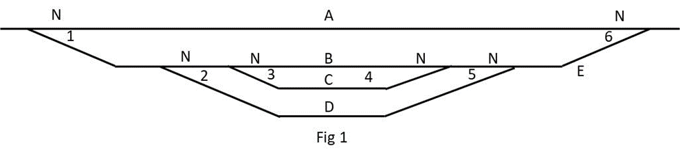
Draw a stick diagram for your yard.  See example in Fig 1.

Number your points.  They can be any numbers.

Letter your routes.  They can be any letters.

Assign a Normal point alignment. (The opposite to Normal is Other).  It can be either alignment.
Route Truth Table

Draw a truth table for your routes. Using pencil and paper will do.  List your route codes and, for each, write in the points along the route and an N or an O to indicate their necessary alignment.


Note. Route E lets trains in or out of the yard while not needing to change point 1.

Matrix Step 1

Draw a matrix with route letters down the left and the point numbers across the top, indicating their Normal and Other alignments, as in Fig 3.

Use your truth table to fill in the matrix for each route by inserting the letter “L” (Link) in the N or O column for each point required to be aligned.

Matrix Step 2

Look in every N and O column.  Where an L appears more than once in a column, change every L in the column to a “D” (Diode).
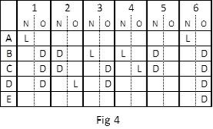
This matrix now provides the logic for your route system. We need to add the other components.

 Capacitor Discharge Units

Capacitor Discharge Units (CDUs) ensure reliable firing of multiple points without burning out your push buttons. They are cheap and easy to build. You can buy them from model shops or build one for less than $5.


Some routes have many points to be switched and others only one or two.

In this example, routes B and C have six points and route E only one.  If you had a CDU capable of firing six points, its power would eventually destroy the single point in route E.

The solution is to use multiple CDUs.  Electrically, it doesn’t matter whether there are one or a dozen CDUs in the matrix system.

You use your matrix diagram to decide how many to use and which points to switch with each one. Try to keep to a maximum of three points per CDU.

In this example, two CDUs are used.

Completed Matrix Diagram

Fig 5 is a representation of the matrix, the point motor coils, the push buttons, the CDUs and the wiring to connect all components. The diagram forms a good template to work from when you are wiring up your system.

Where there is an L, you connect a piece of wire from the route button to the appropriate motor coil. Where there is a D, you connect a diode. The diodes isolate the route buttons from each other.

1N4001/4004 diodes are used. They are black with a white band at one end, the cathode end.  With the CDU output polarities as shown, the diodes must be connected with the banded ends towards the route buttons.      (CDU input wiring not shown for clarity).

Also, to make the diagram easier to physically match to your CDUs, you can move the point number columns back and forth across the page to line them up under the CDU operating them. In this example, it just happens that the numeric sequence nicely splits in two with a maximum three for each CDU.


Board Components

Use a piece of Veroboard to wire the matrix.

To make it neat, portable and to minimise soldering, use combinations of two and three interlocking PCB terminal mounts, available at Jaycar, to make terminal strips.

In this example, you will need one 5-terminal strip for the routes and two 6-terminal strips for the N and O motor coils. 


You will be positioning the components on the insulated side and inserting the terminal pins, diode and wire ends through the holes to solder on the copper side.

Two-Dimensional Magic

Hold the Veroboard with the copper tracks running left to right and study the diode matrix diagram and the copper tracks.  It is possible to wire the two dimensional matrix using only the horizontal tracks. 

Fig 7 represents the three terminal strips positioned on the insulated side, with their pins pushed through their holes. The horizontal lines represent the copper strips on the other side of the board.

Note that the O terminal block is positioned one track below the N terminal block. 1N, for example, is on a different track to 1O.

This arrangement, therefore, enables wires and/or diodes to be connected from a particular route track to any coil track, totally insulated from any other track.  Eg, a wire link from the track that the route A terminal is soldered to, to the track the 1N terminal is soldered to is a unique connection, touching no other track.  

You space the N and O terminal blocks depending on how many wires and diodes you need to fit in the space between.


Matrix Board Wiring

Fig 8 shows the layout of the matrix board for this example and the following connection instructions are for this example. Your board, of course, will depend on your diode matrix diagram – your equivalent of Fig 5 – but the procedure is the same.

Firstly, using Figs 5 and 8 as a guide, lay out the terminal strips, the wire links and the diodes on the insulated side of the Veroboard.  Arrange an optimal spacing and provide for possible future expansion of your yard.

You will probably find that the span for some diode connections is longer than the diode‘s lead length. With these, solder a length of wire to one end of affected diodes.

When you are happy with the layout, double check the locations then push the terminal strip pins through their holes, turn the board over and solder them.

Use a marker pen to write the terminal names on or near the terminals to help with accuracy when making the connections.

Using a wire link or diode, make your first connection.

In the example, insert a piece of wire, cut to length, into the holes along the tracks that route A and coil 1N are soldered to. Turn the board over and solder them.  Work your way through all connections, making sure to connect the banded end of the diodes to the route terminal tracks.

Double-check as you go.

When you have finished, your board should look like Fig 8.


Wiring the System

General

Peco point motors draw quite a lot of current.  To ensure reliable switching, you need to use good cabling and have your cable runs as short as possible. Use cable such as Jaycar WB1708, Heavy Duty Figure-8, which has a black trace on one of the pair.  To help with accuracy, use the black trace side to always connect to the N (Normal) side of the matrix board and point motors.

Locate your matrix board so it is central to the point system with cable runs about the same, and locate each CDU so it is central to the point motors it is serving.

Avoid soldering-in components to the circuit.  Use terminal strips such as Jaycar HM3194 12-way Terminal Strip. You make terminal blocks for the components by cutting the number of terminal pairs you need from the 12-way strip. 


You solder to the point motors and push buttons (and CDUs if they don’t have terminals) but screw-connect to the terminal blocks for interconnections.  This way, you can easily remove components for repair or maintenance without unsoldering anything. 

Point Motors

You wire the point motors before installing the point.

Pick one side of the point motor, either side, and solder individual leads to each of the two solder pads. The other side of the point motor is going to be the common, so strip the insulation from a lead, long enough to span both solder pads, and solder the lead to both pads.  It’s best to use a different coloured lead for the common. 

Push the leads through the hole in the baseboard and install the point. 

Cut a 3-terminal section from a terminal strip, and mount it close to the point.

Screw the common wire into the centre terminal of the terminal block and the other two into the end terminals, as in Fig 10.  Standardise on using the centre terminal for common.
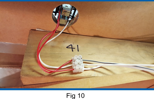
Use a 12V source such as an old train controller to work out which coil produces the N alignment.  Manually align the point to the O alignment then, with one controller lead on the common terminal, tap one or the other active terminals to see which one causes the point to change to N.

When you have determined the N alignment, mark the terminal with a marker pen.

At this time, also write the point number on or near the terminal block. 

Using Fig 5 as a guide, run figure-8 cable from the outer terminals of the terminal block to the N and O terminals for this turnout on your matrix board.  For consistency, use the wire with the black trace to connect terminal block Ns to the N terminals on the matrix board. 

Complete the point motor wiring by running single wires from the centre terminal of all point motor terminal blocks to the positive terminal of the CDU serving them. If the CDU does not have on-board screw terminals, connect its outputs to a terminal strip marked positive and negative, and wire your point motors to the terminal strip positive. 

Interconnections

Design and build your push button panel.  (Doing this is outside the scope of this article.) 

Position two terminal blocks close to the panel, one for the routes with a segment for each route and one for a common. Label the route terminal block with the route codes.

Solder leads to the push buttons and connect one side of each push button to its position on the panel route terminal block. 

Connect the other side of each push button to the panel common terminal strip.  If necessary, make a  multi-segment common terminal strip by connecting wire joiners between the terminal positions. 

Refer to Fig 5 for guidance. Run single wires from each position on the panel route terminal block to the appropriate position on the matrix board route terminal block. 

Run a single wire from the panel common terminal block to the negative terminals of the CDUs. 

Final Testing

That completes the wiring for the system. 

If you have checked everything as you go and are guided by Fig 5, it will work first time.


However, the following may happen:

It works but some routes are not right. 

Check  the truth table logic to verify that a route should work. Check whether the point terminal blocks are correctly labelled N. Check that the diodes are connected the right way around. Check the polarity of the CDUs relative to the way the diodes are wired.

It works but some points in a route don’t switch reliably.

Try adjusting the little slider near the throw-bar of the point. Sliding it back makes the point easier to switch.  If this doesn’t help, add more capacitance to the CDU or increase its voltage supply.  This topic is covered in a separate document. Simple CDU circuits can be found on the Internet.

When you have it all working correctly, give yourself a pat on the back and run some trains through the yard.

Erik Bennett 26/07/2021


Tuesday, August 2, 2022

NCE DCC Update/Changes & WFD-30 from WiFiTrax.

On 2nd August 2022, a modeller on the NCE DCC@Groupsi.o gave a reference to a Podcast by the   "A Modellers Life", hosted by Lionel Strang (DCC Mady Easy fame etc) and his cohorts, where they interviewed Jim Scorse, the owner of the NCE DCC system. Hear the the Podcast at:

https://youtu.be/WCTVJVEpM-Q

Jim Scorse made some announcements about new things for NCE DCC system that I've listed below.

1. The Power Pro has a software upgrade, done last year. I've noticed on the new Command Station Upper Circuit Board, the EPROM is Jan 2022.

2. The Wireless system instead of having just the one frequency of 916 mHz, it will have 14 Channels, that's 14 different frequencies for the U.S. & Canada and fewer for Aust & N.Z. Dividing your Throttles into different channels will reduce latency of the data getting to the loco's decoder and it'll be backwards compatible. The release date is the end of Summer 2022 in the U.S but NCE is waiting for the 14 channel Radio Modules. Details to follow.

3. Jim Scorse also said they will release a new DCC system that is being held up by the parts shortage issue. 

For me and many others, these changes will only make a small difference to the way we operate our model railways. Mostly for large layouts with lots of Operators e.g. Clubs etc.

I will be getting the latest EPROM upgrade for my Power Pro & the details of what changes/additions have been made.

In the interview Jim Scorse mentioned the WFD-30 from WiFiTraxx as an alternative to purchasing Wireless Throttles. Purchase a WFD-30 and plug it into the Cab Bus (UTP) etc. Download the applicable APP (Engine Driver for the Android & WiFi Throttle for the iPhone), now you can run trains, saving the layout owner purchasing an RB02 Radio Base Station & Wireless Throttles. Now everyone can operate "untethered" - how good is that and you don't have to have a computer loaded with JMRI or a Raspberry Pi connected to the layout (system).

I have had one of these since they were first released  some years ago, located at the end of my Workbench,  

The basic setup will support 4 Mobiles/Throttles, more than for most of us, but configuring it to be a Network using your Access Point, you can have more mobiles. From my previous Workshop Blog entry, 


I've included Craig Mackie's 2  comprehensive write up for using the WFD-30, below: 

Part 1: http://ca55ino.blogspot.com/2020/05/wifitrax-wfd-30-nce-cab-bus-wi-fi.html

Part 2: http://ca55ino.blogspot.com/2020/05/more-on-yesterdays-wifitrax-wfd-30.html

For more details on the WFD-30 & other products, see the WiFiTrax web at: http://www.wifitrax.com/


Monday, June 27, 2022

Control Panels on my Main North Upper Deck.


Adding the 48s to Werris Creek and Willow Tree, I needed to motorize all the Points to make it all work for running the 48s. I had to redo the track for the Diesel Terminal to fit the Peco Point motors, as the initial track layout was done in a hurry & it is hard to reach/see the position of the Points. When I added Willow Tree, I added the Point motors & components as I laid the track & even added the ballast.

Finalizing South Werris Creek & Willow Tree was a real challenge as I had to prepare for a hospital procedure in April that took me out of action & when returning, resulted in a major lack of motivation on the Main North. 

I replaced the round table in the Family room with a 2 metre table I had downstairs & 4 chairs I found while walking the streets for exercise that the owner had put out for a council pickup. 

With the extra bench space, I set up my wife Elley with her Puzzle Books etc & purchased her a Laptop to look at YouTube videos etc, at one end & setup my Laptop on the other end. 
We now have plenty of room so the two of us can bash away at the keyboards together. Better still we're together as we face the challenges of getting older, together.


Last year, I'd already drawn up some basic plans of the 3 Control Panels I needed to make on pieces of paper. I needed to redo these in full scale. I'd previously made a crude Drawing Table using a piece of 300 mm wide timber, a Tee & a crude Set square for the the 45 degree angles, necessary for drawing up my Control Panels. Now that the 3 Control Panels are made and installed, I've decided to make a Control Panel for West Tamworth, I'll add step by step photos below.

All the parts can be purchased from Jaycar: 3.0 mm Aluminum Sheet, 3.0 mm  Green LEDs, LED Bezels & all sorts of Toggle Switches, I use mostly DPDT. If a Semaphore signal is involved, I use a 3PDT unit. I've accumulated many Toggle Switches from the layouts I've dismantled including 4PDT units.

To operate the Peco Point Motors I made a 22.0 Volt D.C. home made Power Supply years ago & it's located under Broadmeadow. This Power Supply already powers Werris Creek and Port Waratah Control Panels so I just extended the 22.0 Volt feed going out to South Werris Ck, Willow Tree & onto West Tamworth.

Using a circuit, I saw in Dec 1994 AMRM from Gary Snow (shown right) - thanks a lot Gary for making operation of my Peco Point motors easier, I solder 2 x Diodes (IN4004 1 Amp Diodes) & test the Motor & Point at the Bench. Occasionally one Motor needs a little more power, done by adding a second 2,200 uF Capacitor. 
Two wires are soldered to the "free" end of the two Diodes across the Solenoids. 
The Negative of the 2,200 uF Capacitors are soldered to the Negative 22.0 Volt Bus.
One of the above two wires soldered to the Positive of the Capacitor, the other wire to the Control Panel Toggle Switch. These two connections may have to be swapped around to get correct orientation of the Point - done on the final installation.

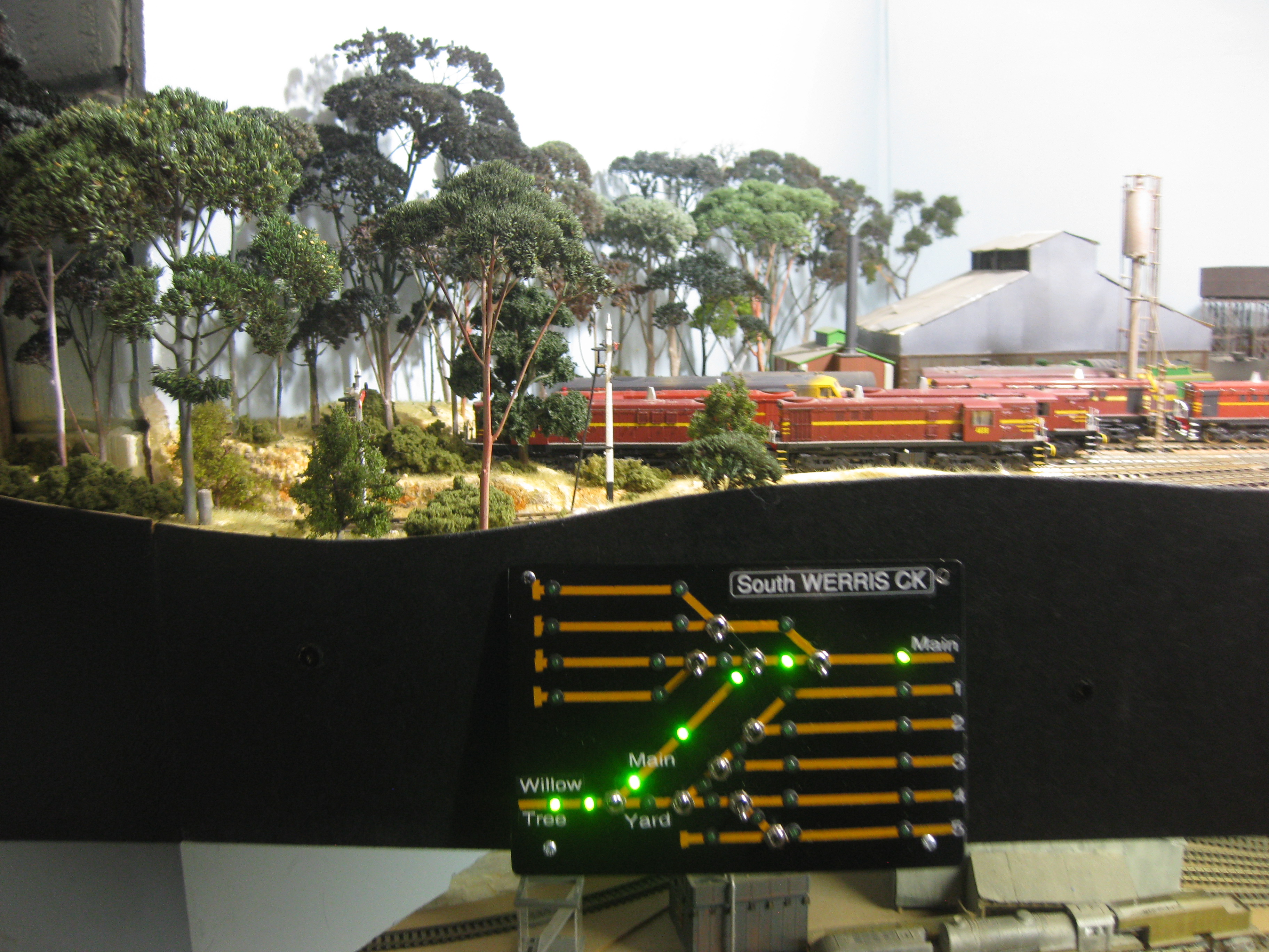
Mounting of the Control Panels depended on the location. The South Werris Ck panel was mounted with a hinge so as it was easily accessible for wiring etc onto two brackets for a sloping Panel. The Willow Tree Panels due to the heavy people traffic in the aisleway, were mounted recessed behind the Fascia similar to how I mounted the Armidale & the Newstan Mine Panels so as they would not be fouled by an Operator. Doing this was a little more difficult but worth the effort.

I moved the South Werris Ck Signal Box further down the Main towards the Station, across from the Turntable. This provided more of a Hill that divides Werris Creek from Willow Tree at the doorway into the garage where Willow Tree is, 


I added more Trees I got off a Mate around the rear of the Werris Ck Roundhouse & I crowded the Sidings with Trees, shown below, maybe not like the real Werris Ck but my Werris Ck is small and needs prettying up & trees do a wonderful job here. The Two Werris Ck UP Starting Semaphores are hard to see with all the new trees but Operators have to vigilant when driving the trains. I added a higher Fascia along the Yard to accommodate the Control Panel.


Werris Ck & the two Willow Tree Control Panels are installed & working as expected with the "route" shown with the appropriately illuminated green LEDs. 


Willow Tree North Panel with the route shown by the green LEDs taking the Operator (train) along the "through" road into Werris Ck.


Willow Tree south Panel showing the selected route along the "Trough" road what I call the Main & not passed the Station. This configuration also illuminates the North Willow Tree Panel as shown above.


At the South Werris Ck Panel, I mounted a 3 Terminal 12.0 Volt Regulator powered by the 22.0 Volt supply onto a piece of aluminum for a heatsink, making a 12.0 Volt Bus going to each Control Panel for the operation of all the LEDs. This Voltage Regulator could be bypassed by installing a Resistor dropping the 22.0 Volts to approximately 12.0 Volts for the LEDs. I may add a resistor at the West Tamworth Control Panel, as the Heatsink is hot to touch & the current to the LEDs is 420 mAs.


Constructing the West Tamworth Control Panel.

Using the appropriate Plan I make a Control Panel from the Aluminum Sheet & I taped the drawn up "plan" to the Plate. I centre pop the location of the all the holes for the Toggle Switches and numerous Green LEDs for route identification, 


Drill the appropriate holes - 6.5 mm for the Toggle Switches & 4.3 mm holes for the LEDs. 


Then spray paint the Panel Yellow.


Using some 3.0 mm Lining tape purchased from Auto One, join the appropriate holes for the track & add dead ends if necessary. I did make a mistake here, I just blacked out the yellow track - easy.


Paint the Panel Black.


Remove the tape to show the Yellow "tracks". Install the 15 Toggle Switches & 54 LEDs


Now for the hard part, the LEDs need to be wired up to illuminate the appropriate route/Siding etc via one of the Poles of the Toggle Switch using a DPDT/3PDT or if a Semaphore is used. This requires lots of effort but worth it the end. I then wired up the Point Motors, connecting all of the 2,200uF Capacitors to the Negative wire of the 22.0 Volt supply under the layout.
 
The most important route is the Return Loop, powered by a Dual Hex Juicer from Tam Valley acting as an Auto Reverser, located under the track.

The West Tamworth Panel with the appropriate Sidings etc named using a Brother Printer. Operating the Glen Innes Mail, into  West Tamworth, I leave the Barraba Mail Coaches at the Station then run the Mail into Armidale. If the Mail needs to be "turned" for operating as the UP Mail, then take the Return Loop. Back up the Mail via the Crossover into the Shunting Neck. Then into the Station. Then "back up" into Armidale ready to operated as an UP Mail, stopping at West Tamworth to picking up the 3 Barraba Mail Coaches on the way through plus double heading 3009, through to Werris Ck.

With the Return Loop being the most used section of the track at West Tamworth, I fitted a 15 Volt 3 Terminal Regulator at the suggestion of a Comment left below, to reduce the temperature of the "heatsink". The current to the 18 LEDs at 12 Volts was 270 mAs & with the 15 Volt Regulator it reduced to 210 mAs. The temperature of the heatsink is just luke warm now. 


The recessed Panel located in the fascia on the Down end of the Station with the Silo in the background with the 3 Sidings storing the RU Wheat Hoppers.


Behind the West Tamworth Control Panel - what a mess but it works. All the White wires go to the Peco Point motors.


At the UP end of West Tamworth (3 Loops), there won't be a Control Panel as the Double Slip that's not used much with the only used Point for the "middle" road being used for the Barraba Mail Coaches. If necessary to operate the RU Wheat hoppers or from the Shed, then this will have to be done manually.


All trains are set to run into West Tamworth Station by Occupancy detectors on the Lift Up Bridge with the Bracket Semaphore also indicating to the Station. There is a Bracket Semaphore indicating the route through the Points into the Return Loop or to Armidale. I need to set up something automatic if Continuous running is necessary. I have to think about this as Return Loop running is the major operation here.


The operation through to the UP Main from West Tamworth is done automatically with Occupancy detection & Point Motor Accessory decoder, Marcus' version, see below: 


The first 5 months of 2022 were quite wet with more mold prevalent downstairs. I spoke to a mate that suggested purchasing a Dehumidifier. These were scarce in June but I was able to purchase a Delonghi unit easily moved around the layout with the 4 casters, is now sucking out all the water in the air & hopefully reducing any new mold. Water has to be emptied from the onboard 4.5 litre tank unit but I can connect a hose for continuous draining, if necessary. 


Friday, June 24, 2022

How Lucky are we Model Railroaders.


Yesterday, Friday the 24th of June I was invited by Bob, one of my train mates to a Meeting of his group of model railroaders that have been meeting for years for a lunch & a catch up. I have been included into Bob's group as a Visitor, a local & somewhat familiar with DCC & electrics. I hope the others don't mind. I am a member of a few other groups where we used to run trains prior to Covid, once a month, the Friday Night Ramblers at Eureka Models, the NMRA & SCMRA.  

These daytime Meetings there's a little running of trains but more importantly the host kindly provides lunch mostly from the BBQ. The Host obviously gets a hand with what is served up but Members bring grog & lots of cakes. 

I've had the privelidge of Meetings at Bob & other Members homes but today I saw another one.

John has a Shed in his backyard for his very finely detailed O Scale layout where all rolling stock & locos were scratchbuilt/kitbashed. We're all getting too stiff for the Duck Under, so I don't know how you do it John. I did ask Bob, John was into HO with layout/s in the spare bedroom etc years ago & before that as a Collector. Some years ago he ventured into O scale. 

The Members here in this group organize trips away etc. I remember Bob going to Melbourne with the Group to see Puffing Billy that was instrumental in him now modelling Puffing Billy HOn3? Just today Ross was organizing a compartment in a train to the Maitland Steamfest. 
Members of the group are shown in the photo outside John's Shed.

While in years gone by, train talk & plenty of Banter was the conversation, today there was a bit on men's health. It is a sign of the times. One of the group Kev, I met when I was working for Qantas.

Ross bought a DVD along on Steam on the South by ARHS but we ran out of time. 

We are indeed lucky to have so many model railway friends. The comradery in the Hobby is one of the things I treasure the most. Thanks Bob for including me & taking me under your wing today. I will pass on the trips but would love to host a get together one day. Quite unusual, I was very quiet today, even with a mobile, I didn't take any photos. 

John thanks a lot for the great get together.    

Saturday, November 20, 2021

Willow Tree

In the early days of my Main North, I had ear marked Willow Tree on the 30 feet of track from Ardglen to Werris Ck, with the intention of adding/removing Bankers on some of my trains, but it didn’t happen due to the track being 1700mm off the floor. Without the banking operation being done, this section of track remained a single line. I added a Shunting Neck & Loading Bank for Werris Ck, operated from the doorway in the Trainroom. Note: The garage floor is 300 mm lower than the Trainroom floor. 

To get better operation of trains at Tamworth and the Werris Ck Shunting Neck/Loading Bank, I extended the Trainroom floor down the aisleway, providing an operating height of 1400 mm, shown left with me operating at the new Willow Tree. 


I installed a Step down to the floor, 2/3rds the way down the aisleway, to keep the Duck Under height at 1700 mm, making it easier for Operators to duck under the Duck Under.


Introducing the 48s to Werris Ck (a previous Blog entry), I wanted to add a 48 Banker to a double 48 hauled 1,000 ton BWH Wheat train. I replaced the Werris Ck Shunting Neck/Loading Bank with Willow Tree so I could add more of what I love doing, operating “Rear End Bankers”, to some of my UP trains, even if it was just a short “bank” around the corner into Ardglen. It’s all about operation.


I added a “scenic block” to divide Willow Tree from Werris Ck, at the doorway by adding a Hill, a road bridge and plenty of trees.


This available space was only 3 metres long, not ideal but compromises have to be made when building a layout, so it’ll do for my Willow Tree and the Bankers. The below photo from the Ardglen end shows my overall view of Willow Tree with my extras. Lots more detailing necessary.   


On the Down side of the Station, I added a Siding for a 60’ Turntable, Coal Stage and Sheep Pen with Ramp. The Middle track is the “through” road and the aisle side track is a Siding with a very compressed Good Shed, a Loading Ramp and a Wheat Shed.


Looking towards Ardglen shows the Station, the middle “Through” road and the Siding, with the severely compressed Goods Shed, Loading Bank/Crane and Wheat Shed into the available 50 mm, better than not having them. Adding a higher fascia helps with the "compression". The “old” Werris Ck Coal Mine, in the distance. 


Instead of removing the Werris Ck Coal Mine, the folks at Willow Tree now have a Mine that’ll be serviced by LCH Coal trains to/from Gunnedah (N.W. Staging) and Werris Creek.


Willow Tree will have 4 Starting Semaphores (yet to build my new brass units from Ray Pilgrim), for the middle “through” road and rear “Platform” road & a Down Home Bracket Semaphore above the Duck Under that'll show “the road” for the Points into Willow Tree.


With Werris Ck just "next door", it's Down Home Bracket signal is located at the exit of Willow Tree just before the Road Bridge, indicating to the Operator which road is selected when entering Werris Ck (Main to the Station or to the Yard). Maybe a Willow Tree UP Home will be added in the Cutting on the Werris Ck side.


When adding Willow Tree, I added Peco Point motors to all of the Points and ballasted the track with Chuck's Ballast, so the scene is "complete". With no Control Panels installed for the Points, they are operated digitally with the Index finger, that's possible when using Peco Point motors.

A year later making ControI Panels, I made 2 for Willow Tree, click here for my Control Panel Blog entry

With the 48s now in Werris Ck, the BWH Up train stored at the Werris Ck Silos has been increased to 1,000 tons (16 BWHs & Van). Double headed 48s haul the train from the Silos, through W.C. Yard to Willow Tree, stopping at the Up Starting Semaphore as the double 48s need assistance up the 1 in 40 grade to Ardglen. A second Operator takes the banker 48 and attaches to the rear. Both Operators now "run" the train up to Ardglen, like it did in 1967, see the below 5 minute video.