
I needed to "electrify" the Peco Points in Sydney Staging due to the difficulty of seeing which way a Point was set and to manually changing it, through the Cutout in the fascia at the R/H end of Sydney Staging made worse since adding two extra Sidings. I didn't want to use the DCC solution of Accessory Decoders & a Mini Panel. This was an expense that I didn't need. More so now that I'm a Pensioner not unless I get a cash handout from my Kids, that's very unlikely.
Some time ago my mate Erik suggested using a Diode Matrix where pressing one Button would set all the appropriate Points to give a route through that Loop, similar to how the NCE DCC solution does it with a Mini Panel. I was familiar with Diode Matrix as I used them before.
Erik wrote an Article about Building a Diode Matrix & it was published in the NMRA Mainline magazine. Reading the recent Mainline online, I read Erik's Article that's available at: https://nmra.org.au/3d-flip-book/mainline-2022-issue-4/ starting on Page 20, I was reminded that I should use this method to to electrify my Sydney Staging Points.
On all of my Control Panels I use one pole of 3PDT Toggle Switch to energize the Peco Point Motor's solenoid, using a 2,200 mF Capacitor & 2 Diodes. The second pole to operate a Semaphore Signal & the third pole to illuminate Green LEDs on the route selected. Since there are no Semaphore Signals in Sydney Staging I could use the Diode Matrix solution as described by Erik. I have plenty of the Peco Accessory Switches that'll do for illuminating the Green LEDs for the appropriate route.
I got Erik to send me Word copy of his comprehensive Article with plenty of schematics (Truth Tables) and started building a Diode Matrix to "control" the Points in Sydney Staging. With Erik's permission I've included his Article at the bottom of this Blog Entry. Click on the pictures/schematics in the Article & they display full size on your screen.
Transposing my "Diodes & Links" according to Figure 8 in Erik's article, making sure the Diode's Cathode (Band end) is facing towards the Switch (Negative - ground) onto the Veroboard (available from Jaycar), electrifying Sydney Staging was started.
Operating Peco Points requires the use of Capacitor Discharge Units as explained in Erik's article. I built my own CDUs per an article in a Talking Electronics magazine "Six BD679 Projects", using Veroboard again, using a BD681 transistor, 3 Diodes & 2,200 uF Electrolytic Capacitor. I also added a LED & resistor. My experience of operating Peco Points Motors, you may need a second/third Capacitor especially if you're using the Accessory Switches, that I intend to use to indicate the route through the Yard/Siding by illuminating Green LEDs, Cost per CDU about $3.
A rough Track Plan below including the two extra Sidings indicated by "F" & "G" that initiated the "electrifying" of Sydney Staging using Erik's Diode Matrix. I used Numbers instead of Letters, signifying the Route Number.
.JPG)
You'll have to read Erik's article to understand what the below 2 diagrams show/mean.
.JPG)

.JPG)
I made soldering all the wires from the Pecos to the Diode Matrix, easier by screwing a bracket with a small top secured to the Wall. Secure the Veroboard with a screw. Now it's much easier to solder wires to the Header Pins.
Erik used two CDUs but I decided to make one CDU per Point, I did not want any issues. Making them all on the same piece of Veroboard was easy, I just copied what I did on the CDU above. The row of push button switches on the bottom of the Diode Matrix make it easy to configure the wiring for the correct orientation & are connected in parallel with the Control Panel Push Buttons. Shown, some CDUs are using 2 Capacitors with No 9 using 3, soldering the Capacitor onto the Copper Tracks (backside) of the Veroboard.

.JPG)
Adding two Sidings
Running the 20 BCH Coal train to the Balmain Powerhouse from Port Waratah, terminated at Sydney Staging. This train needed to be "off stage" for the conversion of the Coal to Coke, for the run north to the Newcastle BHP Steel Works, I added a long Siding inside the Return Loop so as this "burn off" could happen. In real life a Coke train ran from the Metropolitan Colliery south of Sydney.
I very roughly fitted some white timber short length of boards to the "inside" of the Sydney Staging Return Loop to make a long enough Siding to store the Coal/Coke Train. While at it, I added another smaller Siding to store another train. These two Sidings come off Loop 4 (the rearmost Loop) at the R/H end by adding two R/H Points with a radii of the Siding being 20 & 18 inches respectively.
.JPG)
.JPG)
The Coal train stored away having it's "conversion" to Coke being done with one little issue, all Operators follow their train from Hawkesbury River Station up Cowan Bank and now totally disappears behind the Coke Train running on the Return Loop. Recently one Operator asked if I could add more illumination under Broadmeadow, I re-routed my LED strip, now it illuminates the train in the Siding and once again it is difficult to see the moving train. I assure the Operator the moving train will appear at the Cutout.
.JPG)
Up till now the Points for the 5 Loops were manually operated through a cutout in the fascia but these two extra Points could not be seen or even reached through this fascia Cutout. This Diode Matrix & CDUs, will make this much easier. A Control Panel will added to the below fascia at the L/H side, photo later.
.JPG)
Shunting each of the trains to the end of the Siding, resulted in both the 46s at the Cutout for easy identification of the loco number. Dial up the Number, press the appropriate Fascia Control Panel Button and the road is set for the run north through Staging, for each of the trains. One minor problem Road 5 needs to be clear. I think I'll have to make this the Through Line and re-allocate the Road/Loop 1 to be a siding. Good for the Concentrate Train - we'll see what works okay for the Operators & they'll let me know what's best.
.JPG)
.JPG)
Operation of Point 8 with a Peco Accessory Switch was intermittent even after adding a third Capacitor & replacing the wiring from the Diode Matrix to the solenoids with heavier gauge wire. Fitted a small Microswitch as shown below, Point 8 now works 100% of the time & that's after I removed the third Capacitor. I fitted these small Microswitches to all the Points in Sydney Staging. Note: I use the Microswitch to illuminate the appropriate Green LEDs to indicate the selected road/route through Sydney Staging. On all of my previous Control Panels, the illumination of the green LEDs is achieved by using one of the Poles of the Double/Triple Pole/Double Throw Switch. I haven't used any of the Peco Accessory Switches before.
I've accumulated many Peco Point Motors & Accessory Switches dismantling a few layouts over the years due their owners moving into a Nursing Home or passing away. The Accessory Switches are piggybacked onto the Peco Point Motors, I thought I'd try them in my Staging area. I had intermittent operation of the Point. I wonder if the original owner had issues. Shown below is Point 8 with the Microswitch.
.JPG)
As done in Armidale Staging I made some Occupancy Detectors shown below, to see if the Loop is empty.
.JPG)
If a train is occupying a Loop, the loco draws current even when stationary. The Occupancy Detector will illuminate the bi-colour LED at the end of the Loop to RED, if occupied, as shown in the Panel photo. The Operator will have to select a Loop where this "end" bi-colour LED is green otherwise he'll have to see the Fat Controller.
.JPG)
This addition to the Main North has consumed me for two weeks but making Control Panels does this to you. An Operator may be asked to a operate a train stored in Sydney Staging, to save him the long 4 metre walk to the other end, I add a Control Panel for him to easily see which point needs to be operated, to get going, finding the Address of the Loco on the applicable Operating Card.
Erik, thanks a lot for your Article and your help with this project.
Copied below with Erik's permission is the original Diode Matrix Article.
Build a Diode Matrix
Simple steps for a system to change multiple points with one button press.
You have a yard or section of your layout with multiple points
switched by twin coil point motors (such as Peco point motors).
You want to be able to have a switch panel with a diagram of
the yard, and push-buttons on each route through the yard.
When you push a button, you want all the points along that
route to change.
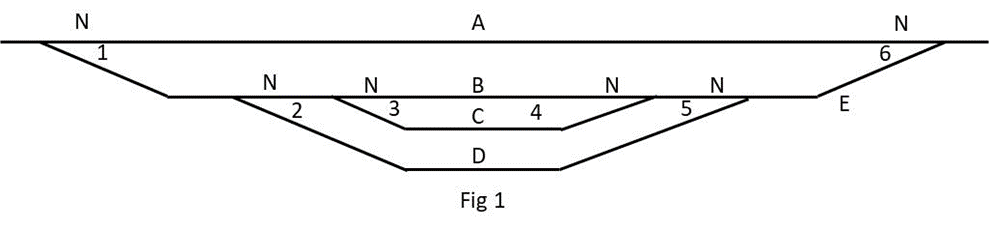
Diagram
Draw a stick diagram for your yard. See example in Fig 1.
Number your points. They can be any numbers.
Letter your routes.
They can be any letters.
Assign a Normal point alignment. (The opposite to Normal is Other). It can be either alignment.
Route Truth Table
Draw a truth table for your routes. Using pencil and paper
will do. List your route codes and, for
each, write in the points along the route and an N or an O to indicate their
necessary alignment.

Note. Route E lets trains in or out of the yard while not
needing to change point 1.
Matrix Step 1
Draw a matrix with
route letters down the left and the point numbers across the top, indicating
their Normal and Other alignments, as in Fig 3.
Use your truth table to fill in the matrix for each route by inserting the letter “L” (Link) in the N or O column for each point required to be aligned.

Matrix Step 2
Look in every N and O
column. Where an L appears more than
once in a column, change every L in the column to a “D” (Diode).
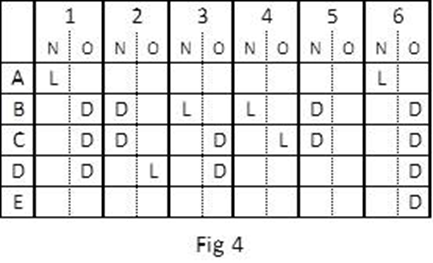
This matrix now provides the logic for your route system. We need to add the other components.
Capacitor Discharge Units (CDUs) ensure reliable firing of
multiple points without burning out your push buttons. They are cheap and easy
to build. You can buy them from model shops or build one for less than $5.
Some routes have many points to be switched and others only
one or two.
In this example, routes B and C have six points and route E
only one. If you had a CDU capable of
firing six points, its power would eventually destroy the single point in route
E.
The solution is to use multiple CDUs. Electrically, it doesn’t matter whether there
are one or a dozen CDUs in the matrix system.
You use your matrix diagram to decide how many to use and which points to switch with each one. Try to keep to a maximum of three points per CDU.
In this example, two CDUs are used.
Completed Matrix Diagram
Fig 5 is a
representation of the matrix, the point motor coils, the push buttons, the CDUs
and the wiring to connect all components. The diagram forms a good template to
work from when you are wiring up your system.
Where there is an L, you connect a piece of wire from the route button to the appropriate motor coil. Where there is a D, you connect a diode. The diodes isolate the route buttons from each other.
1N4001/4004 diodes are used. They are black with a white band at one end, the cathode end. With the CDU output polarities as shown, the diodes must be connected with the banded ends towards the route buttons. (CDU input wiring not shown for clarity).
Also, to make the diagram easier to physically match to your CDUs, you can move the point number columns back and forth across the page to line them up under the CDU operating them. In this example, it just happens that the numeric sequence nicely splits in two with a maximum three for each CDU.

Board Components
Use a piece of Veroboard
to wire the matrix.
To make it neat,
portable and to minimise soldering, use combinations of two and three
interlocking PCB terminal mounts, available at Jaycar, to make terminal strips.
In this example, you will need one 5-terminal strip for the routes and two 6-terminal strips for the N and O motor coils.

You will be
positioning the components on the insulated side and inserting the terminal
pins, diode and wire ends through the holes to solder on the copper side.
Two-Dimensional Magic
Hold the Veroboard
with the copper tracks running left to right and study the diode matrix diagram
and the copper tracks. It is possible to
wire the two dimensional matrix using only the horizontal tracks.
Fig 7 represents the three terminal strips positioned on the insulated side, with their pins pushed through their holes. The horizontal lines represent the copper strips on the other side of the board.
Note that the O
terminal block is positioned one track below the N terminal block. 1N, for
example, is on a different track to 1O.
This arrangement, therefore, enables wires and/or diodes to be connected from a particular route track to any coil track, totally insulated from any other track. Eg, a wire link from the track that the route A terminal is soldered to, to the track the 1N terminal is soldered to is a unique connection, touching no other track.
You space the N and O
terminal blocks depending on how many wires and diodes you need to fit in the
space between.

Matrix Board Wiring
Fig 8 shows the
layout of the matrix board for this example and the following connection
instructions are for this example. Your board, of course, will depend on your
diode matrix diagram – your equivalent of Fig 5 – but the procedure is the
same.
Firstly, using Figs 5 and 8 as a guide, lay out the terminal strips, the wire links and the diodes on the insulated side of the Veroboard. Arrange an optimal spacing and provide for possible future expansion of your yard.
You will probably find that the span for some diode connections is longer than the diode‘s lead length. With these, solder a length of wire to one end of affected diodes.
When you are happy with the layout, double check the locations then push the terminal strip pins through their holes, turn the board over and solder them.
Use a marker pen to write the terminal names on or near the terminals to help with accuracy when making the connections.
Using a wire link or diode, make your first connection.
In the example, insert
a piece of wire, cut to length, into the holes along the tracks that route A
and coil 1N are soldered to. Turn the board over and solder them. Work your way through all connections, making
sure to connect the banded end of the diodes to the route terminal tracks.
Double-check as you
go.
When you have finished, your board should look like Fig 8.

Wiring the System
General
Peco
point motors draw quite a lot of current.
To ensure reliable switching, you need to use good cabling and have your
cable runs as short as possible. Use cable such as Jaycar WB1708, Heavy Duty
Figure-8, which has a black trace on one of the pair. To help with accuracy, use the black trace
side to always connect to the N (Normal) side of the matrix board and point
motors.
Locate your matrix board so it is central to the point system with cable runs about the same, and locate each CDU so it is central to the point motors it is serving.
Avoid
soldering-in components to the circuit. Use
terminal strips such as Jaycar HM3194 12-way Terminal Strip. You make terminal
blocks for the components by cutting the number of terminal pairs you need from
the 12-way strip.

You
solder to the point motors and push buttons (and CDUs if they don’t have
terminals) but screw-connect to the terminal blocks for interconnections. This way, you can easily remove components
for repair or maintenance without unsoldering anything.
Point
Motors
You
wire the point motors before installing the point.
Pick one side of the point motor, either side, and solder individual leads to each of the two solder pads. The other side of the point motor is going to be the common, so strip the insulation from a lead, long enough to span both solder pads, and solder the lead to both pads. It’s best to use a different coloured lead for the common.
Push the leads through the hole in the baseboard and install the point.
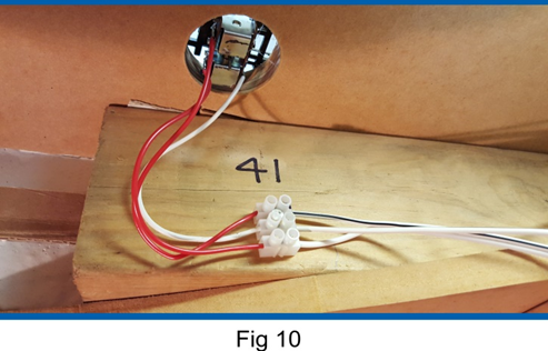
Cut
a 3-terminal section from a terminal strip, and mount it close to the point.
Screw
the common wire into the centre terminal of the terminal block and the other two
into the end terminals, as in Fig 10.
Standardise on using the centre terminal for common.
Use a 12V source such as an old train controller to work out which coil produces the N alignment. Manually align the point to the O alignment then, with one controller lead on the common terminal, tap one or the other active terminals to see which one causes the point to change to N.
When
you have determined the N alignment, mark the terminal with a marker pen.
At this time, also write the point number on or near the terminal block.
Using Fig 5 as a guide, run figure-8 cable from the outer terminals of the terminal block to the N and O terminals for this turnout on your matrix board. For consistency, use the wire with the black trace to connect terminal block Ns to the N terminals on the matrix board.
Complete the point motor wiring by running single wires from the centre terminal of all point motor terminal blocks to the positive terminal of the CDU serving them. If the CDU does not have on-board screw terminals, connect its outputs to a terminal strip marked positive and negative, and wire your point motors to the terminal strip positive.

Interconnections
Design and build your push button panel. (Doing this is outside the scope of this article.)
Position
two terminal blocks close to the panel, one for the routes with a segment for
each route and one for a common. Label the route terminal block with the route
codes.
Solder
leads to the push buttons and connect one side of each push button to its
position on the panel route terminal block.
Connect the other side of each push button to the panel common terminal strip. If necessary, make a multi-segment common terminal strip by connecting wire joiners between the terminal positions.
Refer to Fig 5 for guidance. Run single wires from each position on the panel route terminal block to the appropriate position on the matrix board route terminal block.
Run a single wire from the panel common terminal block to the negative terminals of the CDUs.
Final Testing
That
completes the wiring for the system.
If you have checked everything as you go and are guided by Fig 5, it will work first time.

However,
the following may happen:
It
works but some routes are not right.
Check the truth table logic to verify that a route
should work. Check whether the point terminal blocks are correctly labelled N. Check
that the diodes are connected the right way around. Check the polarity of the
CDUs relative to the way the diodes are wired.
It works but some points in a route don’t switch reliably.
Try
adjusting the little slider near the throw-bar of the point. Sliding it back
makes the point easier to switch. If
this doesn’t help, add more capacitance to the CDU or increase its voltage
supply. This topic is covered in a
separate document. Simple CDU circuits can be found on the Internet.
When you have it all working correctly, give yourself a pat on the back and run some trains through the yard.
Erik Bennett 26/07/2021
I made a diode matrix for the ACT Model railway Society "12th Street Yard", which switched 1 peco point, and 2 double switches. I used a rotary dial to select the route through the double slips, AND the rotary also had the function to energise the various frogs, with the correct DC cab so trains could run off the mainline, into the yard tracks without any extra toggle switches. This was pre DCC. I like your suggestion to use multiple CDUs, as the CDU we were using was not always successful in throwing the 5 peco piont motors.
ReplyDeleteThe same diode matrix concept here, but for Tortoise point motors: https://gmrg.info/wall-const-2009-06.html
ReplyDeleteThe inputs to the diode matrices are pushbuttons, the outputs of the diode matrices connect to driver boards to power the Tortoise motors and move them in either direction. This setup makes the control side low current, with the motor currents handled by the drivers.
Cheers, Martin
Hi Rob and Martin. Thanks for your comments. I'd already experienced "irregular" operation of Peco Point Motors using CDUs. Even in my setup one Point needed a third Capacitor with a couple, needing only one. With this variation in the "energy" requirements, One CDU per Point was the way to go. Martin, my $3 CDUs are my Peco "Drivers" & your included link does not work.
Delete